Here you can find information about what is new in HPOxygen Server version 5.2.22.
HASP HL Driver - Update
After installation of HP Oxygen of version 5.2.13 or later, on running the system you may obtain the error message:
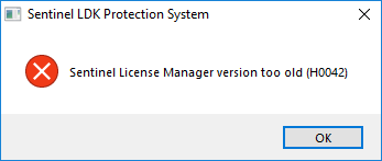
If so, download the newer version installer and then run it. As soon as your HL Driver is updated, you may continue using the system.
Note The driver update will not affect older HPO releases installed on the system - they will continue to work normally.
New AnyCut Workflow
Features described in this section are available for a fee. To purchase, refer to your distributor.
The system now provides the new AnyCut workflow which includes new tools and comfortable user interfaces for registering your own new cuttings from your own designs (ascii, dmc), sample stone scans and successful allocation solutions. The new workflow significantly simplifies both the process of cutting registration and subsequent solution allocation, and also provides extended control over parameters of the solutions. This is achieved by providing the new user interface for user cutting registration, as well as adding a new Recut algorithm paired with the relative appraiser and providing the option of automatic start of SmartRecut basing on the automatically detected best Recut solution.
You can apply the new workflow to any cuttings.
The AnyCut workflow includes the following steps:
- User cutting registration
- Allocation, includes sequentially:
- Recut AnyCut allocation
- SmartRecut AnyCut allocation with relative ASCII appraiser
- (optional) Adding allocation forms
Below these steps are described in an overview video and as step-by-step.
Overview Video
User Cutting Registration
This stage includes obligatory normalization of the model you decided to use as cutting, then registration optimal normalization variant as a new cutting.
- For the scan, you want to register as cutting, run the "18. SmartNormalize" algorithm. Several solutions are produced.
- From the solutions, produced by the "18. SmartNormalize" algorithm, select the one you want to register as cutting.
- Right-click this solution, and from the context menu, select Register as new cutting... The dialog is displayed.
- In the Register new cutting dialog, if necessary, specify Facet Marking.
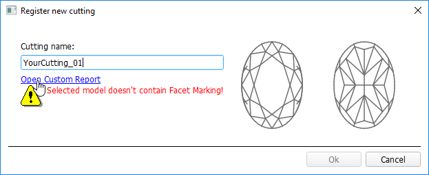
- Set Cutting name.
- Click Ok.
Allocation
This stage includes sequentially:
- Recut AnyCut allocation
- SmartRecut AnyCut allocation with relative ASCII appraiser
The latest version of the system allows executing both steps within one run.
For the Recut allocation within AnyCut workflow, two new algorithms are added to the system:
- 19. Single (FixedForm) - is intended to produce solutions in maximum correspondence with registered forms and limited by these forms number. Better to use when there is a number of registered forms and you want to stick to them. See detailed description of allocation forms in the "Adding Allocation Forms" section below.
- 19. Single (Recut) - is intended to produce solutions for forms and then search additionally beyond them (but in the limits specified by the appraiser). Better to use for searching for larger mass, taking into account that some fixed form solutions may be excluded from results if the algorithm finds better solutions.
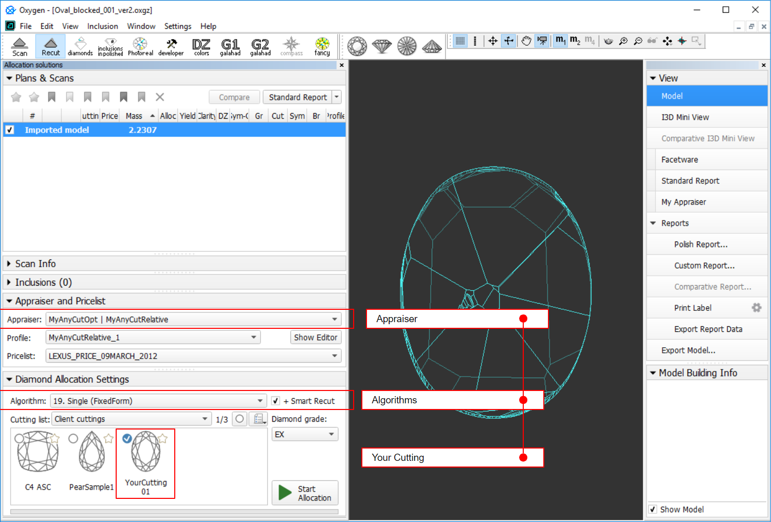
To perform Recut + SmartRecut allocation for AnyCut with your previously registered cutting:
- Set:
- Algorithm = "19. Single (FixedForm)" or "19. Single (Recut)"
- Appraiser = MyAnyCutOpt | MyAnyCutRelative
- Cutting list via Cutting List > Client cuttings = your registered cutting
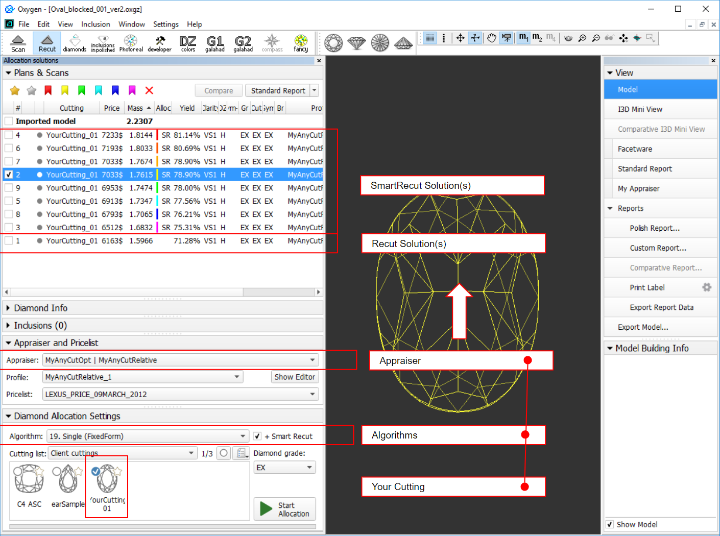
Select +SmartRecut option. With this option selected, from the two best Recut solutions, the SmartRecut will be immediately started.
Note that the SmartRecut algorithm will run with the latest used options. The latest version of the Relative appraiser in addition to others supports Fix Girdle, Fix Crown and Fix Facets options.
- Click Run. Recut solutions are added to the list, then SmartRecut solutions are added.
Adding Allocation Forms
This step is optional as AnyCut is able to run on a single base form (cutting itself). Still, it is recommended to register allocation forms, especially for the different W:L ratio, as it significantly improves allocation results.
For any registered cutting, immediately after its registering or at any moment later, you can add any number of the allocation forms. Each allocation form is a high-quality solution variant for your cutting. Any solutions or normalized scans can be registered as allocation forms for your registered cuttings.
Although the registering of the allocation forms is optional, it may improve the quality of solutions, because on running your registered cutting, the optimization algorithm will check all the included forms trying to produce solutions well allocated with these forms. This means, the more high-quality solutions you register as allocation forms, the better results you achieve when running optimization with your cutting.
To add a new allocation form to your registered cutting, do one of the following:
- To add a new allocation form from a scan:
- For the scan, you want to register as the allocation form, run the "18. SmartNormalize" algorithm. Several solutions are produced.
- Among the solutions, produced by the "18. SmartNormalize" algorithm, right-click the one you want to register as the allocation form.
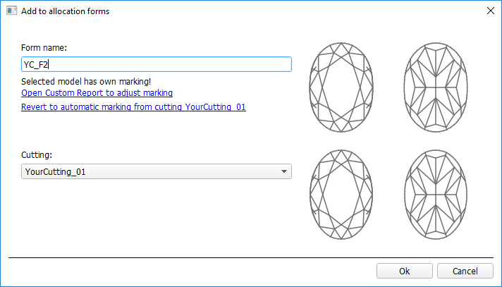
- From the context menu, select Add to allocation forms...The dialog is displayed.
- In the Add to allocation forms... dialog, from the Cutting list, select the registered cutting, you want to add the allocation form to.
- Facet Marking from the selected cutting is automatically applied to your new form. If necessary, adjust the Facet Marking.
- Set Form name.
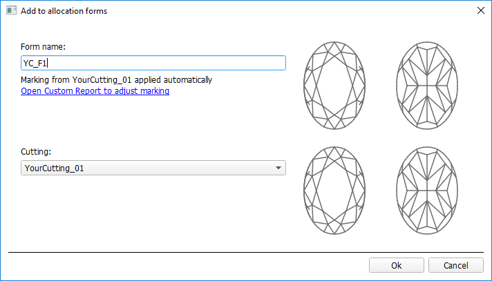
- Click Ok.
- To add a new allocation form from a solution:
- Right-click the solution you want to use as an additional allocation form.
- From the context menu, select Add to allocation forms...The dialog is displayed.
- Further steps are the same, as described above for the normalized scans.
Heights Calculation - New Approach
Handling Extra Facets Adjacent to Girdle
As of August 19, 2019, GIA is using a different methodology for measuring an average girdle thickness. The cut grading system remains the same - only the method used to measure this parameter has changed. The lab was using a method that excluded features such as naturals and extra facets next to the girdle that were not close to vertical. Going forward, the lab is using a method unaffected by any features at the girdle * .
* This thwarts the practice of adding extra facets to artificially reduce the girdle thickness measurements.
This methodology is used in HP Oxygen 5.2.10 and later:
Starting from version 5.2.10, if there are extra facets adjacent to the girdle, the Girdle bezel, and Girdle bone are calculated using the NEW method. The Girdle valley is calculated using the OLD method.
See details in Girdle Heights Calculation Methods
Finding Points on Girdle Curves
For the calculation of the Girdle Bone and Girdle Bezel parameters, it is important how the following points are found:
- Crown bezel point
- Crown bone point
- Pavilion bezel point
- Pavilion bone point
The approach to finding these points has changed.
| Previously | Now |
|---|---|
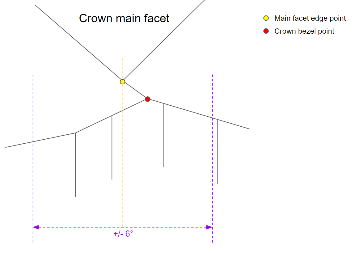
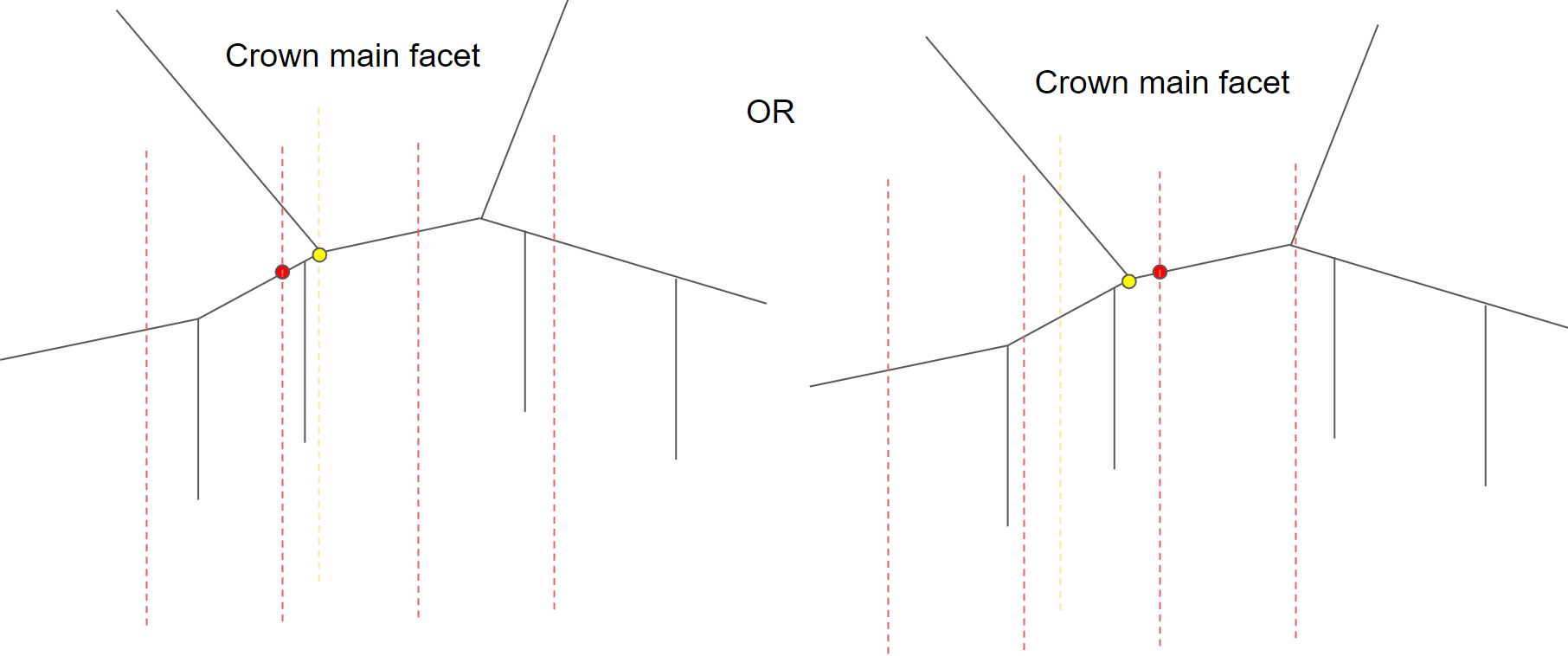
| In case, when the crown main facet does not meet the girdle, nearest (by azimuth) point on the girdle upper curve produced by the 0,5° grid was taken as a crown bezel point . | In case, when the crown main facet does not meet the girdle, the lowest vertex (main facet edge point) forms +/- 6° range, the highest in this range point on the girdle upper curve will be a crown bezel point. It will also be used for calculating the Crown height . The case "does not meet the girdle" includes an extra facet case. |
|
|
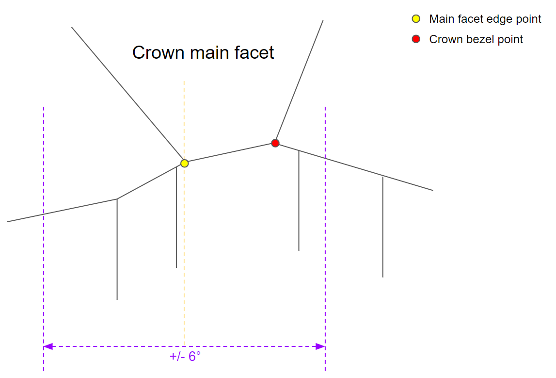
| In case, when the crown main facet reaches the girdle and has one or more common vertices with it, nearest (by azimuth) point on the girdle upper curve produced by the 0,5° grid was taken as a crown bezel point. | In case, when the crown main facet reaches the girdle and has one or more common vertices with it, the lowest vertex (main facet edge point) forms +/- 6° range, the highest in this range point on the girdle upper curve will be a crown bezel point. It will also be used for calculating the Crown height . |
|
|
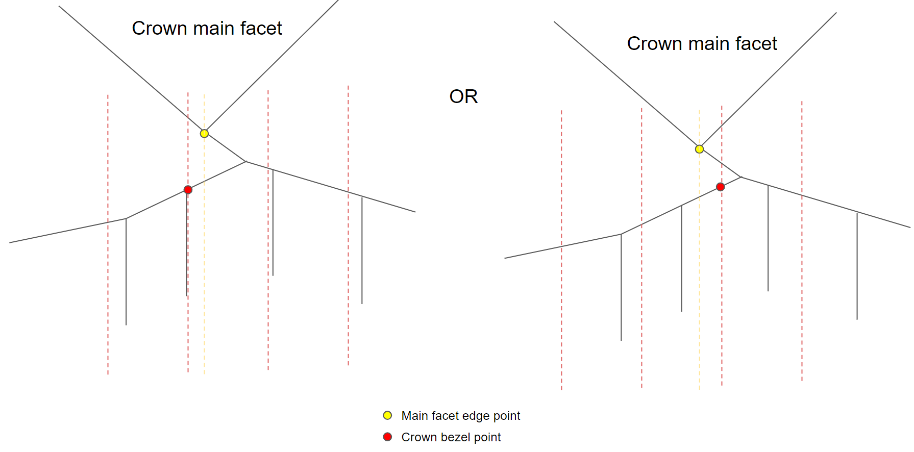
The same approach changes were applied to pavilion bezel points and all bone points.
This change affects also the Crown Height and Pavilion Depth calculations.
Hearts & Arrows Profile and Presets
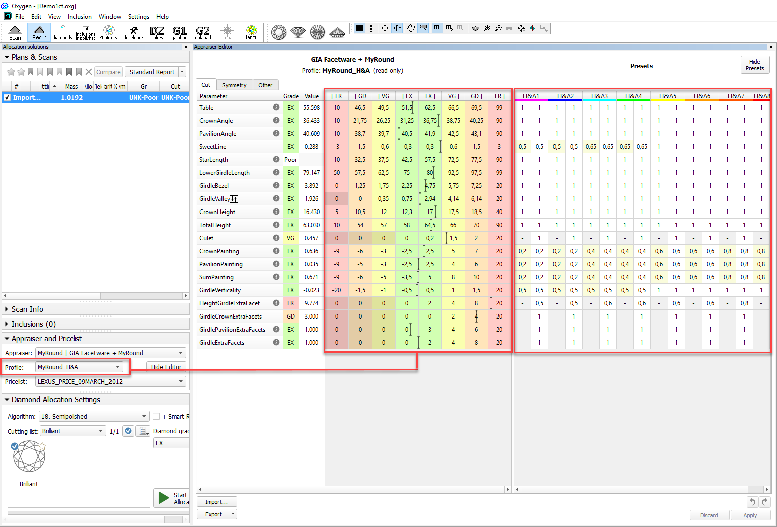
To produce the solutions optimal from the perspective of the Hearts and Arrows ( H&A ) optical symmetry standard, for the "My Round | GIA Facetware + MyRound" appraiser the new "MyRound_H&A" profile has been added. The profile also contains the set of 8 profile-specific H&A presets, that allow getting a variety of excellent H&A solutions within one run for later comparison and selecting the best one.
In the video below you can find some information on how H&A profile and presets can be used and examples of produced solutions.
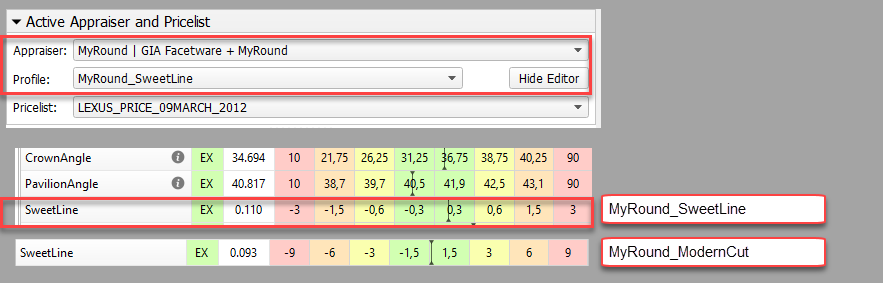
New SweetLine Profile
For the "MyRound | GIA Facetware + MyRound" Appraiser, the new "MyRound_SweetLine" profile is added. The profile is based on the "MyRound_ModernCut" profile but holds narrowed boundaries for the SweetLine parameter, which means it is aimed at producing solutions with better optical performance (see Using SweetLine for details).
Recut and SmartRecut in One Run
The system now provides the ability to apply Recut and Smart Recut algorithms sequentially within one run. To enable, select your Recut algorithm, then select the + Smart Recut option, then start allocation.
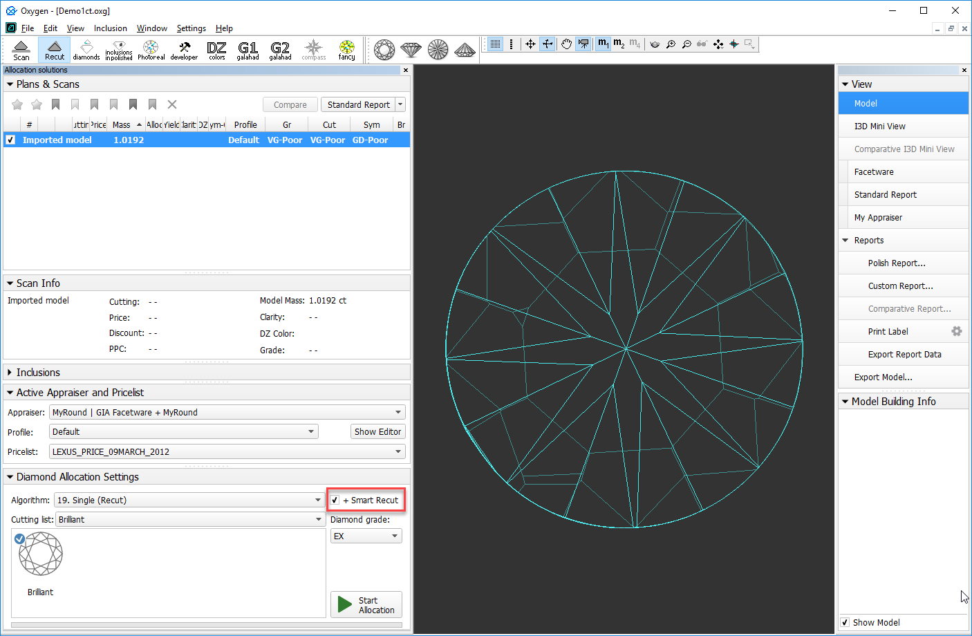
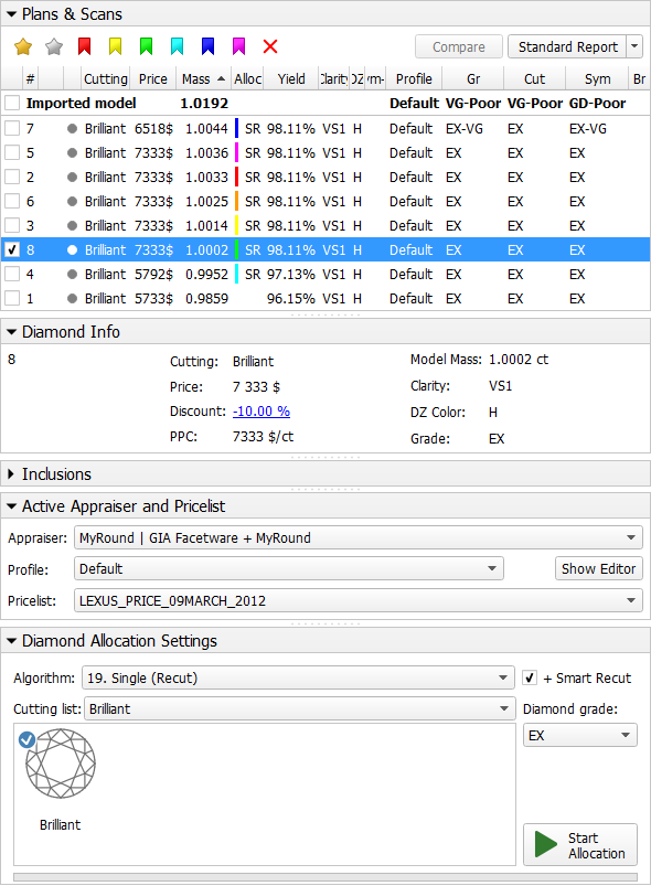
With the + Smart Recut option, the SmartRecut will start automatically after the Recut, basing on the two best Recut solutions. In the solution list, you will obtain both recut and SmartRecut solutions.
SmartRecut starts with the last selected options.
Presets Mechanism Change
Profile Specific Presets
How the presets are used in the system is changed.
| Previously | Now |
|---|---|
| The same presets were shared between the different profiles, thus if you changed some preset, the new value affects all the profiles sharing the preset; you could not use different preset settings for different profiles. | Each profile contains its own set of presets. Thus, if you change some preset, the new value affects only the profile it belongs to. |
|
|
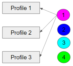
The presets allow producing a spectrum of solutions within one run of an algorithm with this profile. The new approach allows precise configuration of profiles without interference with the other profiles. Each profile now consists of 1) cutting parameter intervals 2) presets values.
Note that the system allows copying both cutting parameter intervals (Cut and Symmetry tabs) and presets values into your own editable profile. There you can further tune them. More explanations about how profiles and presets are used now and examples are presented in the video below:
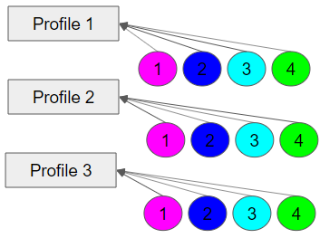
Rename and Color Legend Change
To comply with the color coding:
- presets with the cold colors (short wavelength) - strict
- with the warm colors - extended
...color legend and names of some presets have been changed comparing to previous versions.
Here are the changes spread between profiles of most appraisers:
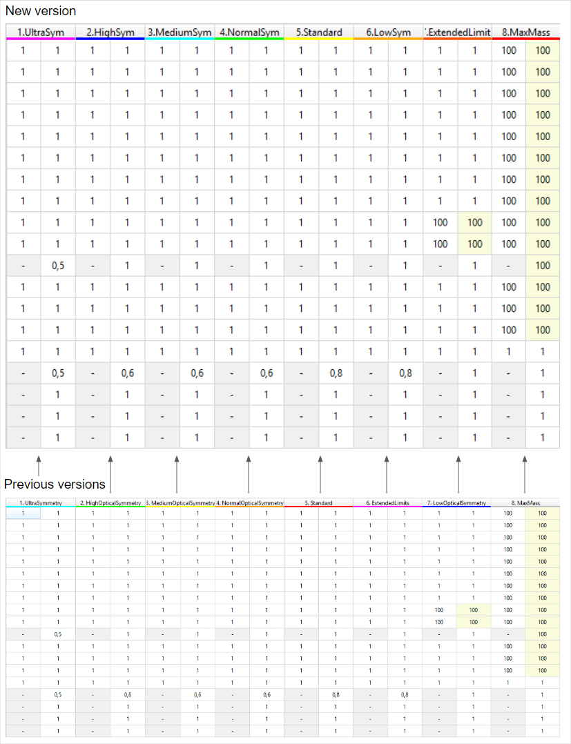
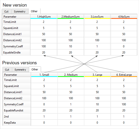
Here are the changes related to the presets used by the SmartNormalize algorithm:
Initial Scanner Settings - Files Update
Attention
For proper functioning of the system, it is required that you download and use the new versions of files.
The files with the initial scanner settings have been updated. You can download the updated files from the page: Initial Scanner Settings
Quick Download
You can quickly download all files listed on the Initial Scanner Settings page as a ZIP file.
Changes:
- For the HP_1 boards:
- The Period has been changed (HPODrivers_Shadow_HeliumSpeed.ini)
- Acceleration presets have been added (HPODrivers_Shadow_HeliumSpeed.ini)
- hws_prosilica.xml has been added - contains settings for HPO Shadow with the Prosilica camera. Now includes two additional elements (by default commented out and thus inactive):
- Under <benchmark_fps>, <!--measure/--> - uncomment to <measure/> to enable the benchmark measurement of the maximum FPS
- <!--packetSize>8228</packetSize--> - for some installations, the automatically set packet size causes video artifacts like missing lines - in that case, uncomment to <packetSize>8228</packetSize> and decrease the initial "8228" until artifacts are gone.
- Under <benchmark_fps>, <!--measure/--> - uncomment to <measure/> to enable the benchmark measurement of the maximum FPS
- For the rest .ini files
- Unused blocks have been removed
- Some elements have been renamed
Interactive 3D Reports Client - Update
The Interactive 3D Reports Client utility has been updated to work properly with the new structure of folders where reports are stored.
To download the OctoNus Interactive 3D Reports Client Setup 1.2.12.0, click here .
Renamed Algorithms
The following algorithms have been renamed:
- 18. Single(Recut) > 18. Semipolished
- 13. Single-M > 13. Single (Rough)
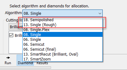
The new names reflect more clearly the difference between the algorithms and help to understand which of them should be used in each particular case.
The "13. Single (Rough)" algorithm produces several different solutions in the different areas of a diamond.
The "18. Semipolished" algorithm finds all the same solutions as "13. Single (Rough)", but selects only one - the best - of them, and then adds one more solution to it, which is aligned to the facets of the initial semicut stone and this solution may be better, especially after applying Smart Recut.
Improved Facet Marking for Standard Cuttings
For allocation results the facet marking now is applied immediately after solution creation; Instead of the Polish Report method with very basic facet marking, the system now uses the pre-installed sample markings specified for each standard cutting.
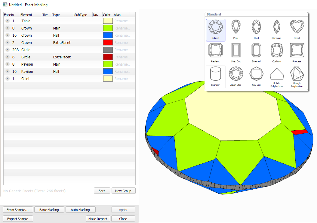
Using the specific marking sample for each cutting makes the resulting Facet Making more accurate and reduces or eliminate the need for manual corrections.
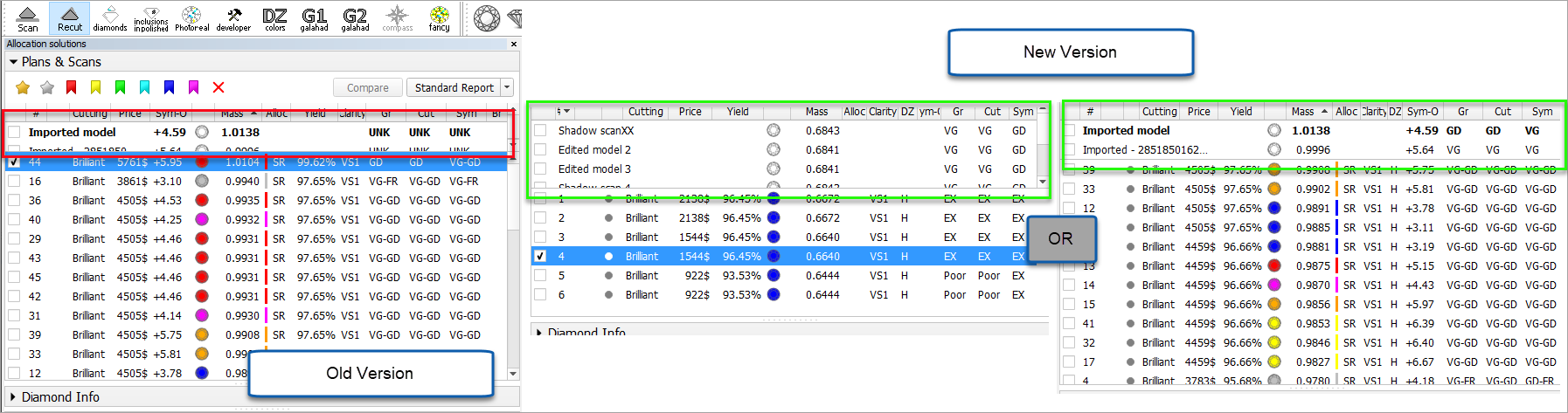
Interface - Diamond Allocation Settings
For the Recut mode, on the left panel, the Diamond Allocation Settings panel now has a new look.
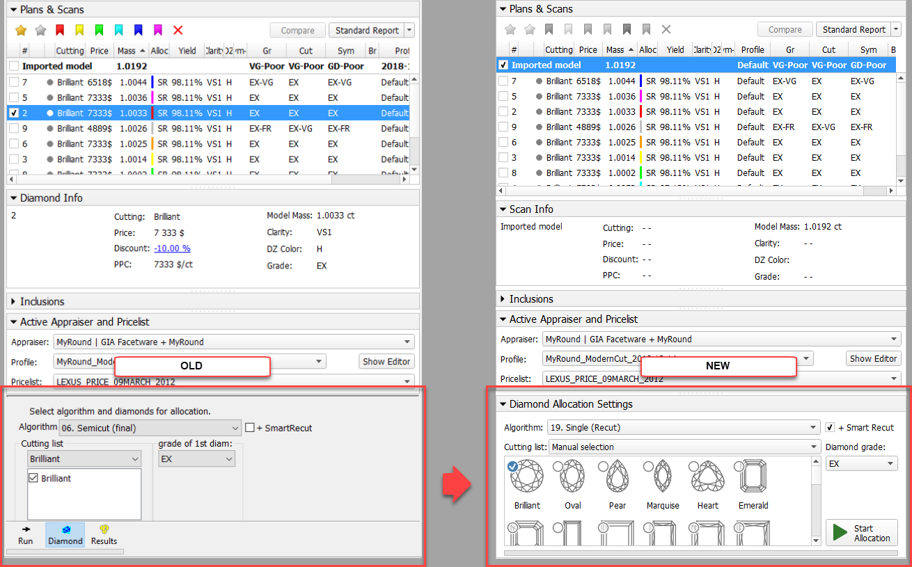
The new interface allows more comfortable work when selecting an algorithm and its options, including cutting.
SmartRecut for RBC - Improvements
For the "13. SmartRecut (Brilliant, Oval)" algorithm, for Brilliant cuttings, the accuracy of the calculation is increased for the following parameters:
- Diameter Avg
- Diameter Dev
- Radius Roundness
- GirdleValley Min
- GirdleValley Max
- TotalHeight Min
- TotalHeight Max
- CuletOffset
- LowerGirdleLength Avg
- LowerGirdleLength Dev
This allowed to significantly improve the main output characteristics of the algorithm - the mass and the quality of the produced solutions - as well as the algorithm work speed. Below you can find the statistics obtained from SmartRecut RBC tests for EX grade.
- The average solution mass 0,11% increase
- The average work time for all 8 presets 20,5% decrease due to reducing of the number of long working presets, specifically presets reaching the TimeLimit
- Getting EX GIA solution in more than 99,5% algorithm runs
- Getting solution strictly within MyGIA boundaries, taking into account the presets multipliers, in 98,7% algorithm runs (it was 95,3 in a previous version)
Manual Editing of Reflect Contours
Now you can manually edit automatically created reflect contours. To access the editing tool, in the  Developer mode, load your Reflect photo set, then use the Reflect tab, Pavilion sub-tab. With the appropriate photo selected, click Manually Click Contour.

After tool activation, you can add, move and delete points with you mouse and keyboard, as described in details in Manual Editing of Reflect Contours.

Finish editing by clicking the Finish button. Save your project via File > Save . Your edited contours will be saved along with the project.
Interface - Magnifier Tool for Photo Views
For the Photos views around the system, it is now possible to enable the Magnifier which represents the area around the cursor in the Scene in an enlarged form.
To enable the Magnifier, from the main menu, select View > Show Magnifier (Lens). The Magnifier is displayed in the top right corner of the Scene for all Photos views.
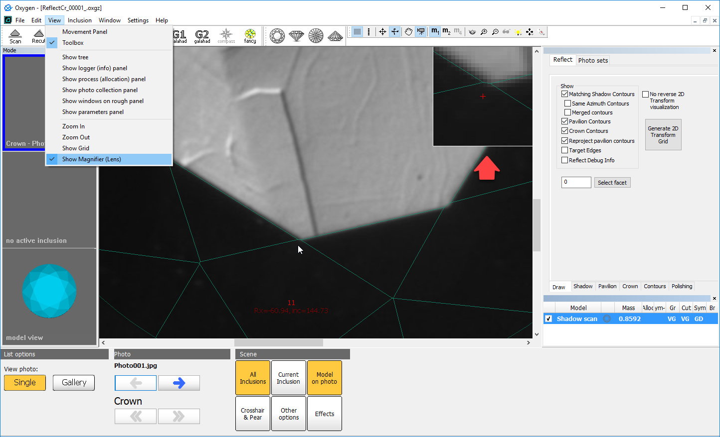
To hide the Magnifier, deselect the option in the menu.
Exported Report Data - Profile and Preset Information
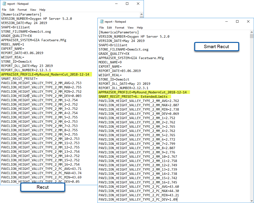
Now to the exported report data file (generated using the Export Report Data function), the following information is added:
- Which profile of the appraiser was used to produce the solution: the APPRAISER_PROFILE element within the file.
- For smart recut solutions - which preset was used to produce the solution: the SMART_RECUT_PRESET element.
I3D Report and Views - Improvements
Multiple improvements have been implemented for I3D Report, I3D Mini View and Comparative I3D Mini View.
Girdle Heights Visualization
Previously lines representing girdle heights in I3D views were positioned incorrectly. Now this problem has been fixed. The positioning of girdle height lines in the I3D views is in correspondence with their representation on the Girdle Thickness graph.
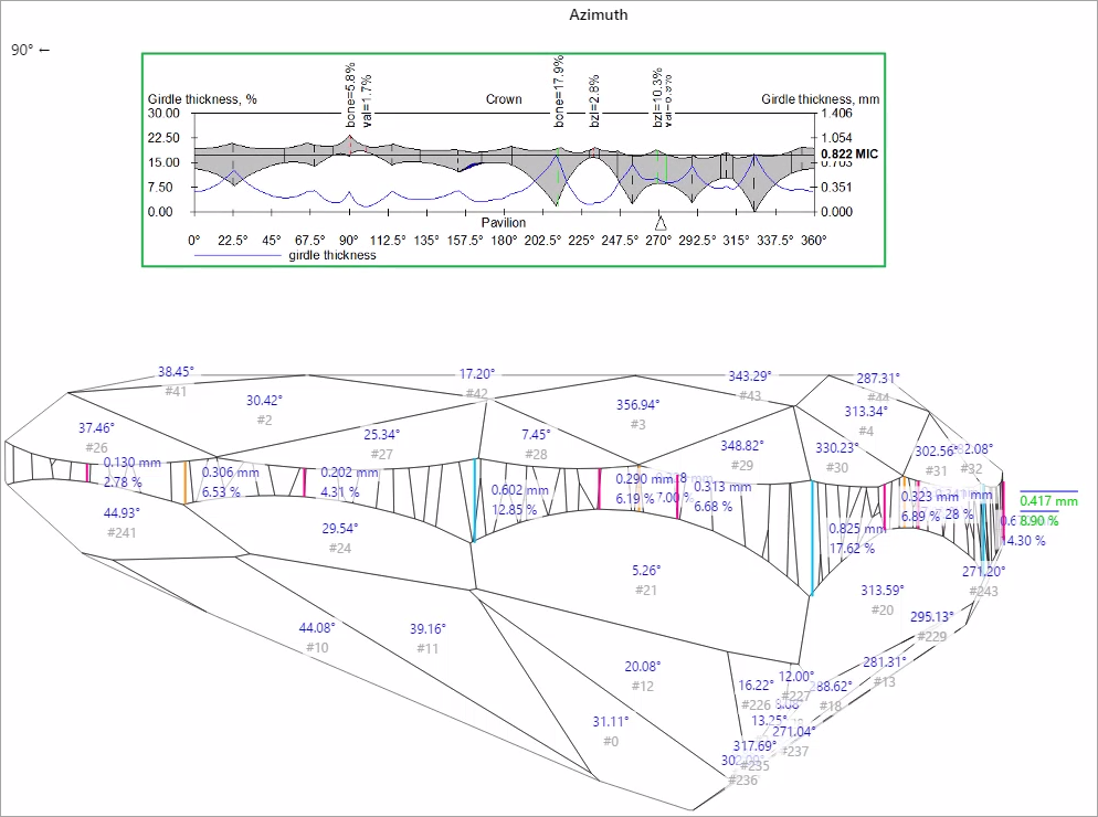
For the additional convenience, now the height lines become invisible when the corresponding facet is not visible in a view.
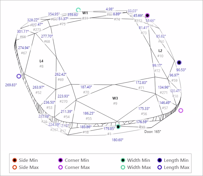
Square Cuttings - New Girdle Heights
For square cuttings, the 4 new groups of girdle heights are added to I3D Report and views:
- Side
- Corner
- Width
- Length
I3D Views - Legend
In correspondence with how it can be done in Interactive 3D report, now it is possible to show/hide Legend in I3D views.
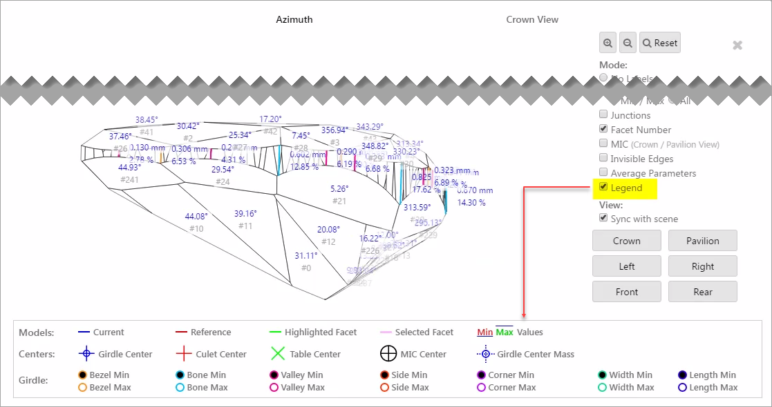
Note that you can select either Legend or Average Parameters to be displayed - but not both of them at the same time.
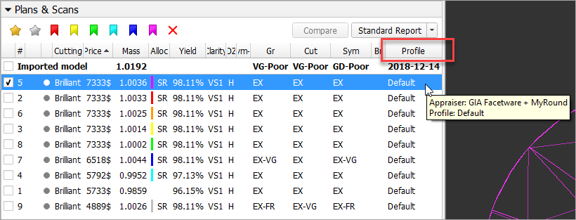
Interface - Profile Information
In the Recut mode, in the solution list now the information about the profile is displayed. Mouse over the solution to get tooltip including an appraiser and its profile names.
Reports - Folder Structure Change
For the Polish, Comparative, Facetware, Custom, Faceting, I3D reports the naming has been changed for the folders storing report results:
| Was | ...\Documents\OctoNus Software\Polish Reports\RTF\Project Name\ XXXX-Project Name \XXXX-Project Name-report.rtf |
|---|---|
| Now | ...\Documents\OctoNus Software\Polish Reports\RTF\ Project Name \ XXXX \XXXX-Project Name-report.rtf |
| ...\Documents\OctoNus Software\Polish Reports\RTF\ Project Name Cropped \ XXXX \ XXXX-Project Name Cropped-report.rtf |
The cropped project name is used when the maximum file path name (MAX_PATH = 260 characters ) is exceeded.
The changes have been implemented to avoid errors caused by the maximum file path name going beyond the limit.
Fixed Problems and Improvements
The following fixes for the known problems and improvements have been implemented:
- For the SmartRecut algorithm, small improvements and fixes have been made.
- An infrequent error in Recognition has been fixed.
- Facet type detection has been improved for scanned RBC stones with lots of extra facets on the girdle.
- Shadow scan failed to start if the stage did not stop rotating. This problem has been solved by building the queue: the system now waits until the stage stops, then starts the Shadow Scan.
- Error with Princess shape wrongly recognized as Square Radiant has been fixed.
- Missing Table for Cushion cuttings error has been fixed.
- Rx motor initialization error has been fixed.
In the Recut mode, the Plans & Scans section was inconvenient to work with scans when there was a lot of solutions. Now this problem is solved.
A periodically appearing error during editing a model edges (using Scan > Edit Model Edges panel) has been fixed.
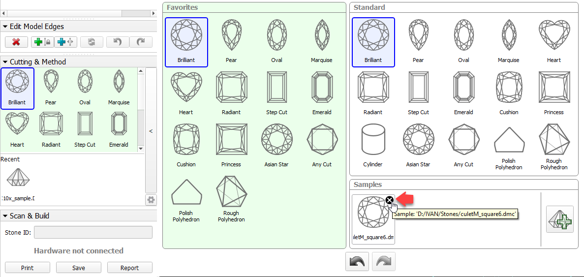
In the Scan mode, in the Cutting & Method section removing from Samples did not work. Now deleting works fine.
Minor improvements in the Crown Reflect basis adjustment have been implemented.
0 Comments