...
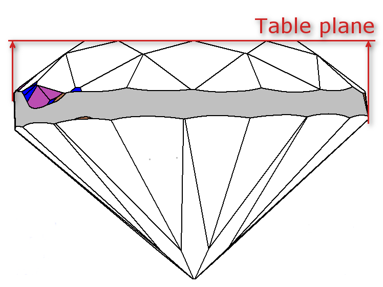
- Draw plane parallel to table plane through MIC center:

- Distance from model center to section-plane calculated for all azimuth.
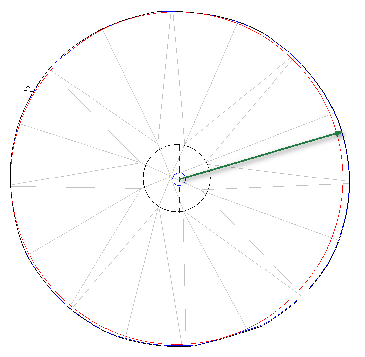

MIC is drawn in red color 
indicates MIC center 
indicated Girdle center mass (model center) - Minimum radius from step 2.2 selected.
- Graphics is drawn as deviation from minimum radius.
...
- Model is projected on table plane:
Distance from model center to projection calculated for all azimuth:
MIC is drawn in red color indicates MIC center indicated Girdle center mass (model center) .
Graphics 3. Graphics is drawn as deviation from minimum radius from step 2.3
...