Here you can find information about what is new in Galahad Compass version 5.4.3.
Public Features
The functionality described in this section is available to users.
On-Screen Information
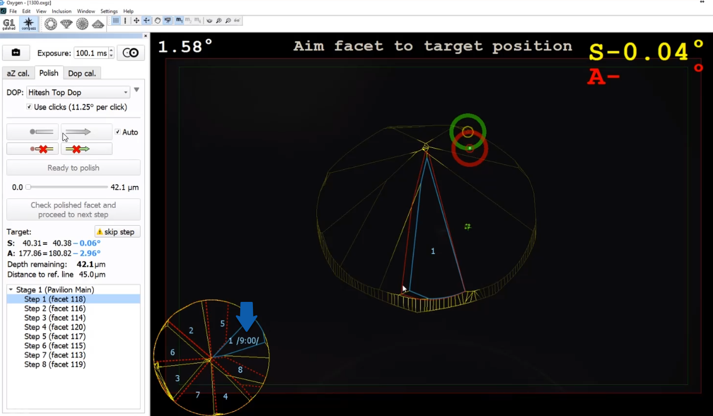
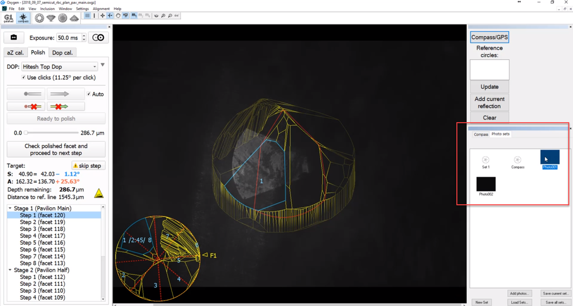
Now the main view of the Scene rotates automatically to place the facet of the current step to the center and highlights it. The numbers of steps mapped to their facets are displayed in the thumbnail view - the number of the current step is displayed in the main view.
Additionally, current instructions and important notifications are also displayed at the top and bottom of the Scene.
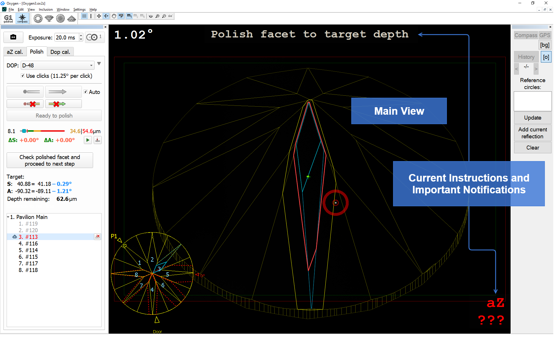
On the main and thumbnail views, the following information is visualized with the lines of different colors:
- Pale Yellow - general model contour
- Yellow - target facet
- Dark Blue - edges of the current reference facet
- Light Blue - current state of the facet being polished (changes on dragging the step slider)
- Dotted Blue - when the slider of the cutting depth goes further from "0", the blue line becomes dotted
- Red - actual cut
- Dotted Red - future contours of all facets
On the thumbnail view, there are some markers:
- F1 is transformed to P1 (for pavilion)/C1 (for crown) - first facet marker
- 0° - of the target stone
- Door - the "door" of the scanned model
As you drag the slider of current step progress, the thumbnail and the main view edge lines are updated dynamically.
Axis Z Calibration Mode
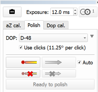
Previously, the axis Z (axis of stone rotation) considered to be normal to the stone table. Testing in real life conditions demonstrated that it was not the right approach: the axis Z was not always normal to the stone table which is revealed on the large rotation azimuths. To eliminate this discrepancy, the Axis Z Calibration Mode has been added to the system. The mode refines the DOP Click Correction mode and therefore is only available when the Use clicks option is selected for the DOP. In that case, the additional aZ cal tab is displayed providing you with the controls for axis Z calibration.
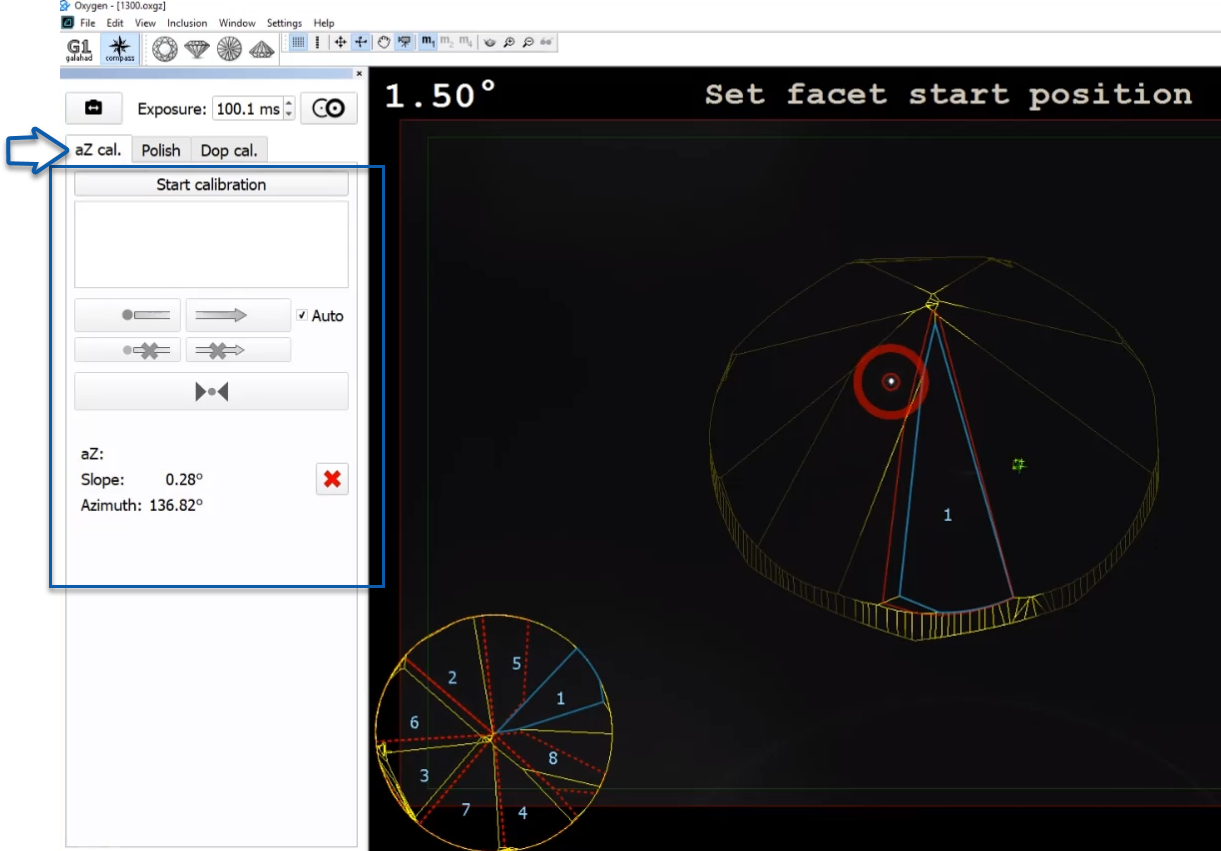
To use the feature, click Start calibration, the system will form the list of facets to take part in a calibration: select a facet from the list, aim to this facet, set facet start position, then  show slope direction, set facet back to start position, show azimuth direction, and then click
 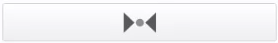 Register selected facet reflection. The system will automatically select next facet to use for calibration and give an instruction on how to switch to it, for example: "Rotate DOP on +8 clicks". You do not need to show slope and azimuth directions again - for the remaining calibration facets only register the reflections.
The expected position of the reflection is displayed in the Scene with the blue ring

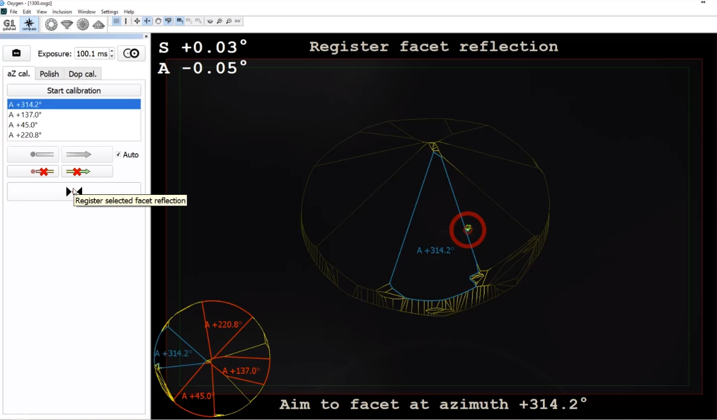
As soon as reflections are registered for all suggested facets, the calibration is finished and the Calibration Mode will be disabled. Calibration results are displayed in the bottom of the calibration tab and in the Scene, in the bottom notification area:
On success - the green line notification will be displayed
- On error - the red line error notification will be displayed saying that the deviation angle exceeds the limit (by default, 5°)
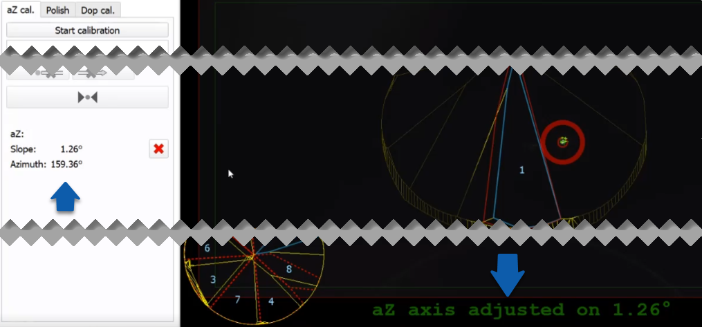
Detailed information about calibration results can be accessed via main menu View > Show logger (info) panel.
You can erase the calibration results by clicking the  button, displayed after calibration is finished.
You can leave the Axis Z Calibration Mode without finishing the calibration. In that case, the collected data will be lost and you will need to re-start calibration later. To leave the calibration mode without finishing the calibration, switch from the aZ cal tab to any other.
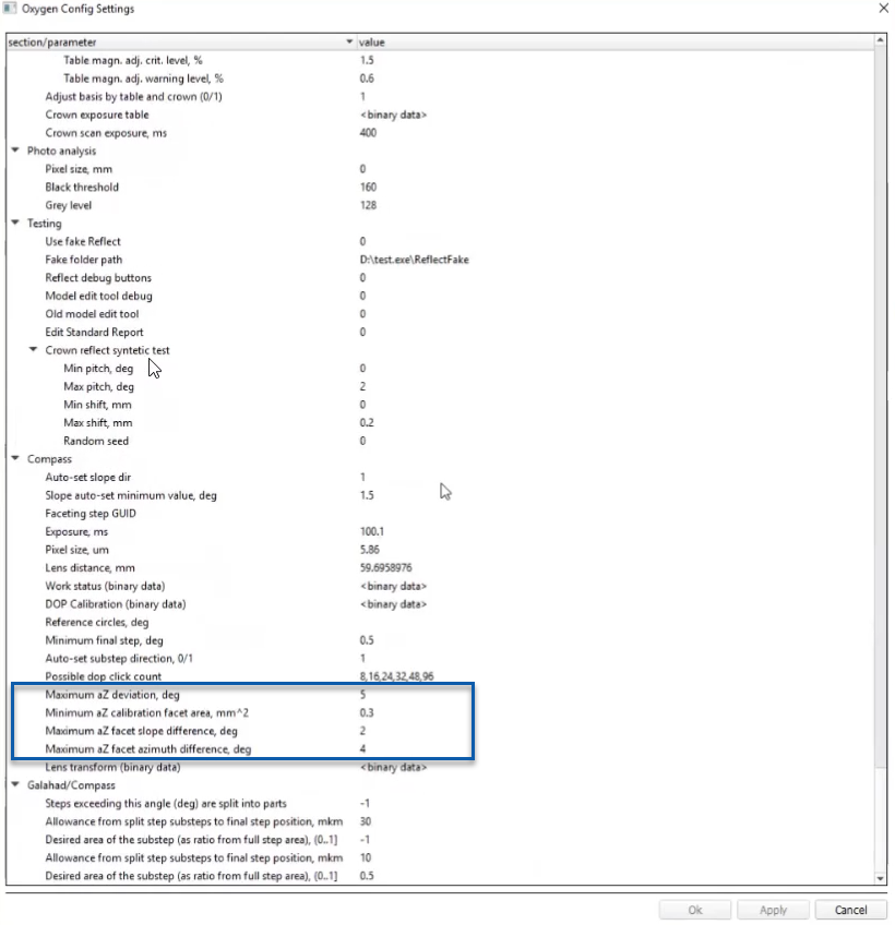
Configuration
You can configure settings below only if specific conditions are met.
To configure thresholds required for detecting the facets which will take part in the calibration of the Z axis, under Internal Configuration, set aZ-related parameters in the Compass group.
Displaying Graining Direction
Now, within the selected step, after you show slope and azimuth direction, the graining direction is detected and automatically displayed in the thumbnail view.
The graining direction is saved together with the project file and remains available on re-opening.
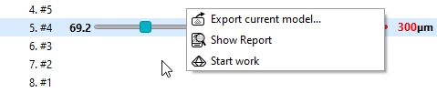
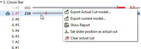
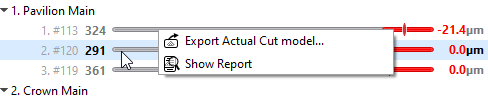
Exporting Actual Cut Model
Now it is possible to obtain a model for the actual state of cut at any moment. This can be done via the context menu:
| Step not started |
|
| Step InWork |
|
| Completed Step |
|
Auto-Registering Direction
Now the "Auto" checkbox allows registering not only slope but also azimuth direction automatically when the current angle value exceeds some threshold level.
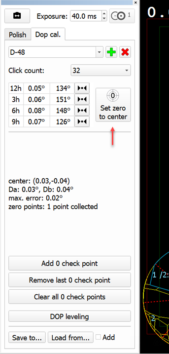
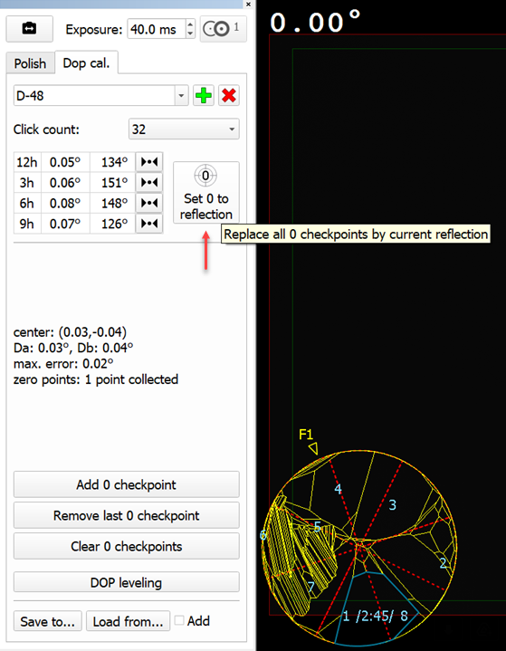
Set zero to... Button - Behavior Change
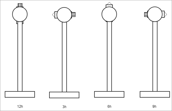
The name of the Set zero to center button is changed to Set 0 to reflection and the action is changed correspondingly - now it sets dop zero to the current reflection:
| Was | Now |
|---|---|
|
|
Lexus Private Details
The information in this section is for sharing with Lexus only.
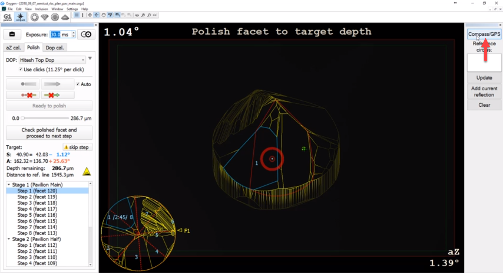
Working with Compass/GPS Cameras
Now the system allows working with two cameras: one providing the Compass image, another - the GPS one (photo of the facet). The cameras work one by one, providing images asynchronously.
To switch between cameras, on the right panel, click Compass/GPS.
|
|
| Compass | GPS |
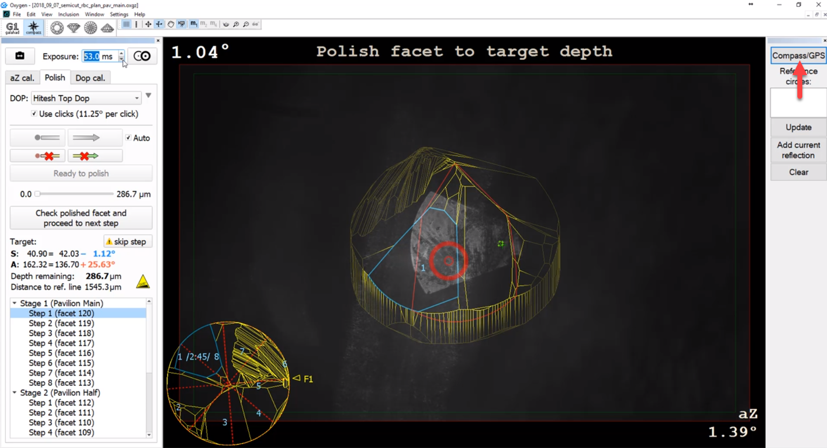
For each mode, you can set its Exposure parameter separately.
You can shoot photos from both cameras. To do so, start the system with the "/alignmentmenu" flag (see details here), then on the right panel, on the Compass tab, click the Shoot button.
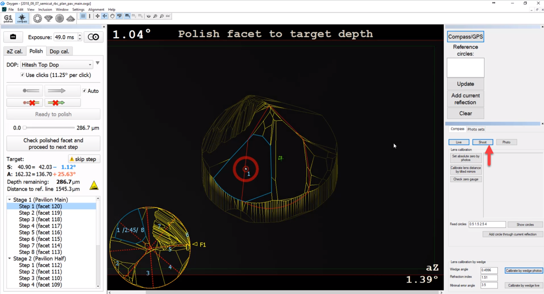
To access taken photos, use the Photo sets tab.
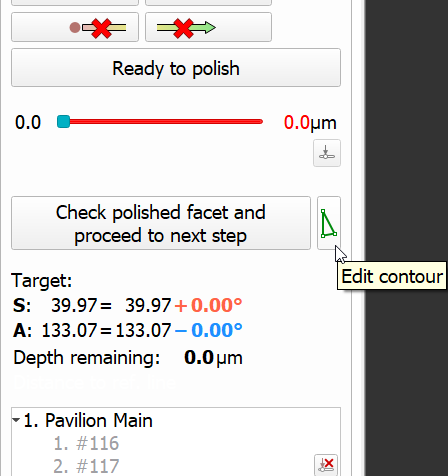
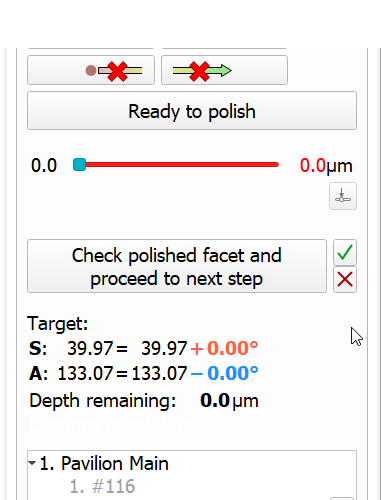
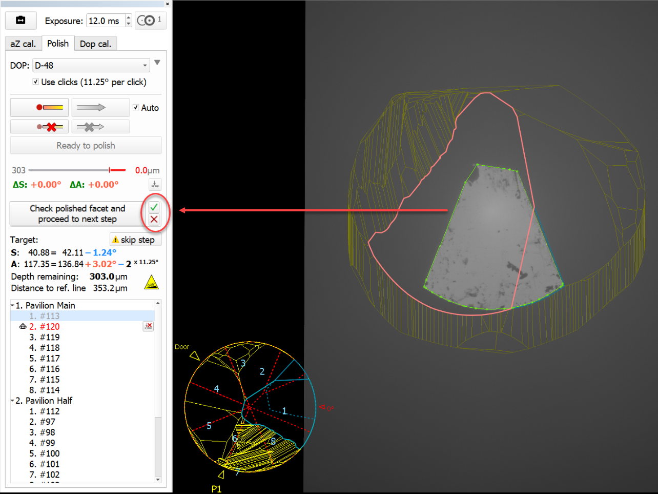
Manual Contour Correction
Now it is possible to manually correct a facet contour. This may be useful for the cases when GPS photos containing graining lines may be imperfectly processed by automatic contouring algorithms.
| Start Editing Contour | Editing in Progress |
|---|---|
|
|
To start editing, click the |
|
| |


Fixed Problems and Improvements
The following fixes for the known problems and improvements are implemented:
- The Standard Report was displayed for the solution and not changed if the scanned item was selected – now it is fixed, the report changes when selection changes in the solution list.