
Galahad 1
Mode "G1 Galahad" is added.

"G1 Galahad" mode allows to visualize virtual steps of cutting process of stone. "G1 Galahad" mode helps cutter to cut facets correctly by visual control of facet shape and difference values of slope, azimuth, distance between plan and current model.
Please watch a small video which shows the basic operations of the new mode:

For a more detailed explainations, see the documentation below:
G1 mode shows main scan and active solution (target plan) from Recut mode:
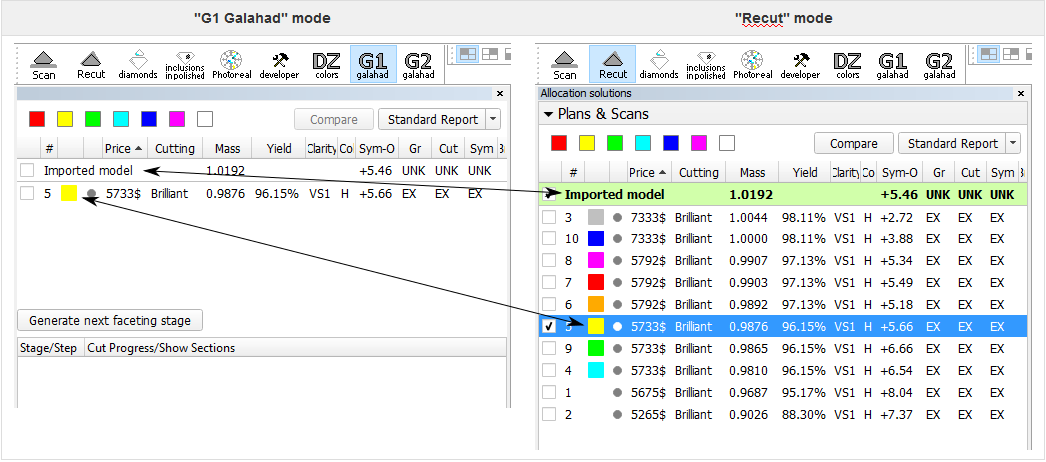
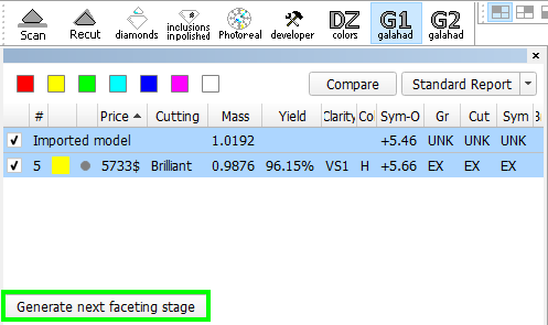
- To generate next steps plan you can either
- right-click on the selected solution in Recut mode, in the context menu select "Generate..." under "Next Step Plans" group
- or click button "Generate next faceting stage" from G1 mode.
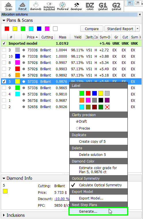
OR
- "Next Step Plans" panel appears, selection of facet type is highlighted by dark green in the scene and first facet of selected type is highlighted by violet.
In the panel "Next Step Plans" operator can configure polishing stage parameters, in the scene operator can select facet type and first facet with a simple click.
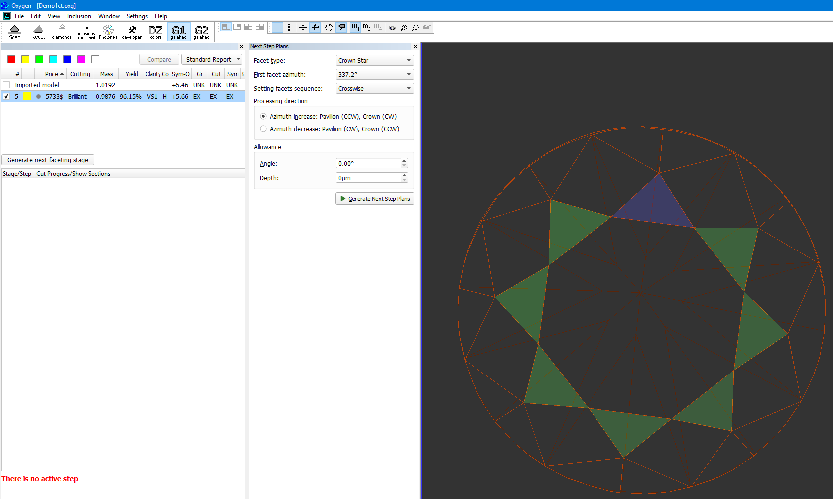
- After configuring the parameters, click "Generate Next Step Plans" button, Faceting Report is generated and opened in the default system browser automatically.
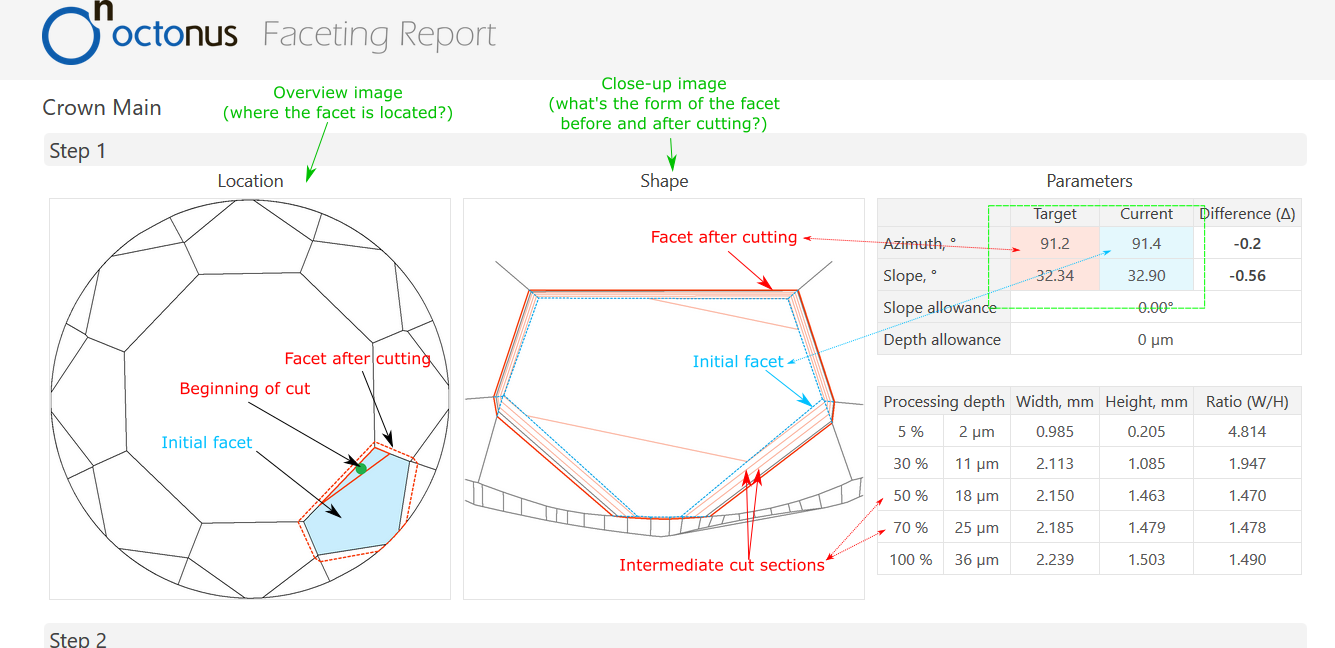
- To view the generated faceting stage, switch back to Helium Polish Oxygen software.The new faceting stage with its cutting steps steps (1 step per facet) appears in the left panel in G1 mode.
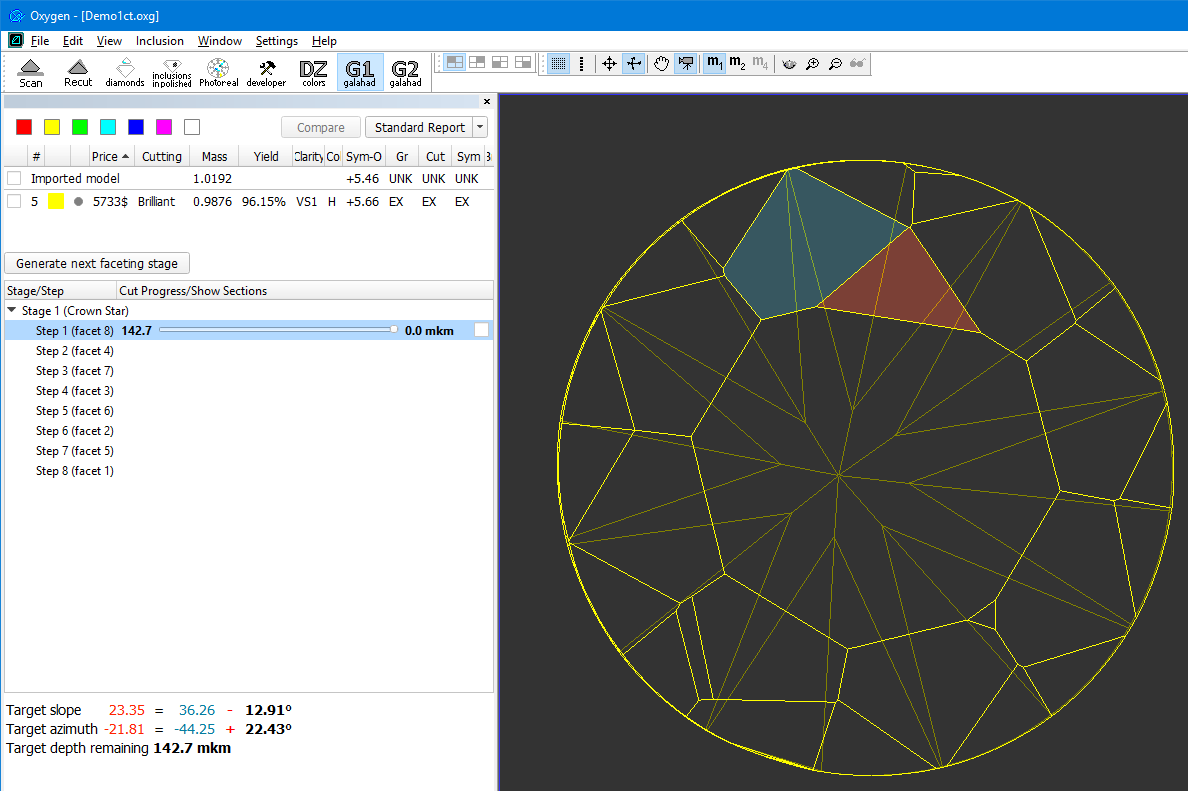
In the Scene operator can see yellow model which correspond to current stage/current step. Current facet under cutting is highlighted by  color. Facet, highlighted by
  color, is the nearest facet to current.
In left panel with stages/steps operator can see slider which by default is the end of scale for each step. Position of slider displays the current depth of cutting and corresponds to the model on the right.
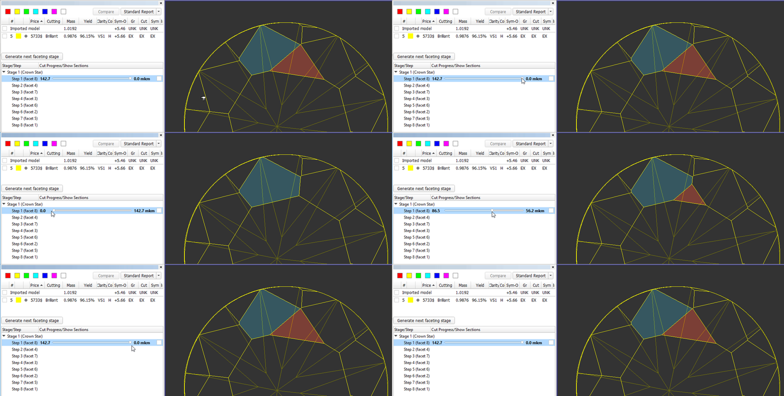
There are values on in the beginning and in the end of scale - they mean distance of cutting which is already passed for model on the right and distance which is left till end.
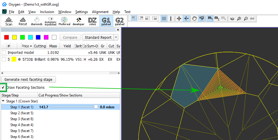
Checking the "Draw Faceting Sections" box shows sections of cutting at 10, 20, 30, ... percent of depth:
- Information under the stages/step shows slope angles and azimuth angles of final plan model and current step model (yellow) and difference between them. Also target depth of cutting is shown:

- Operator can check boxes on the left top table and see in scene plan (red) and original (blue) model:

- After cutting of Stage 1 facets, operator has to press button "Generate next faceting stage" and proceed with next facet group.
- Right click on step item allows to export the current model model to .mme file:

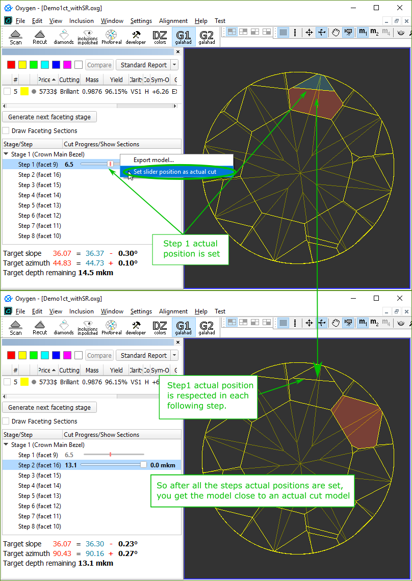
- You can also do a "virtual cutting" by fixing the final position of the step at a value less than 100%. E.g. you are cutting according to this faceting plan, but decide to stop at some point and return to this facet later. So you set the "actual cut" position for this faceting step (facet) and the following steps will use this position as an initial model of the stone. See below:
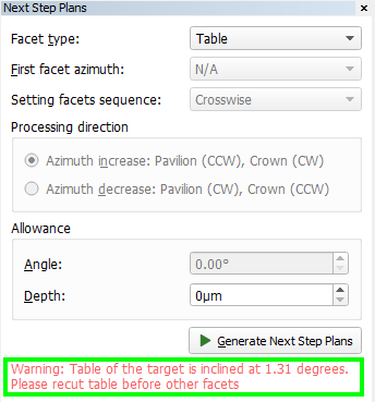
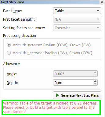
Note: If table of plan is inclined more than 1 degree then alert message to recut table will be shown in panel Next Step Plans. If table of plan is inclined more than 0.1 degree but less then 1 degree then alert message to select another plan will be shown in panel Next Step Plans
Reports
- Option Rotate to door is available by right click in I3D Mini View and in Standard Report: Operator has to scan and build model of stone, open I3D Mini View or Standard Report and then right click on any required facet and press Rotate to door:
![HPOxygen Public Documentation > 2017-12-29 - HPOxygen Server 3.26.11 > 2017-12-11 11_10_33-Oxygen - [Oxygen1].png](/wiki/download/attachments/73537984/2017-12-11%2011_10_33-Oxygen%20-%20%5BOxygen1%5D.png?version=1&modificationDate=1514558660303&api=v2)
![HPOxygen Public Documentation > 2017-12-29 - HPOxygen Server 3.26.11 > 2017-12-11 11_13_19-Oxygen - [Oxygen1].png](/wiki/download/attachments/73537984/2017-12-11%2011_13_19-Oxygen%20-%20%5BOxygen1%5D.png?version=1&modificationDate=1514558660006&api=v2)
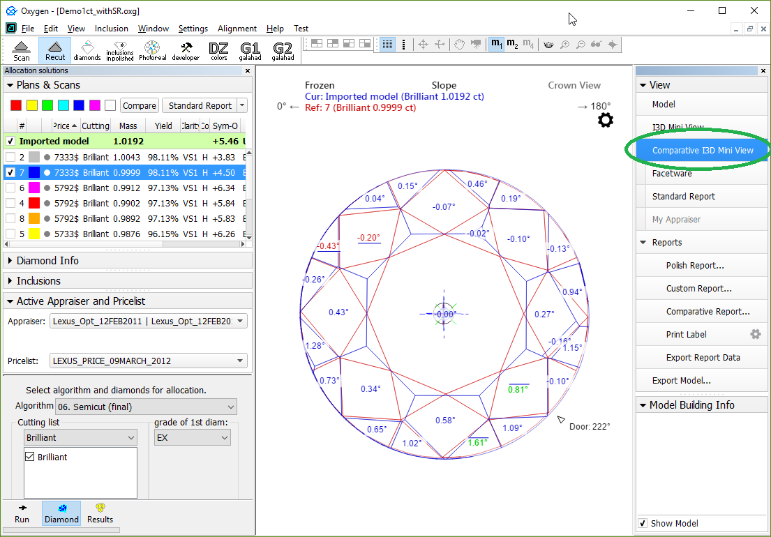
After click scanner will rotate stone with selected facet to door and operator can mark it for further processing. - The Comparative I3D Mini View was added:

SmartZoom
Improvement in 13. SmartZoom algorithm: if table planes of plan and source solution are different on angle more than 0.5 degrees then algorithm 13. SmartZoom rotates plan to make table plane parallel to table of source solution.
So final SmartZoom soltuion will have table parallel to original source table.


 color. Facet, highlighted by
  color, is the nearest facet to current.


![HPOxygen Public Documentation > 2017-12-29 - HPOxygen Server 3.26.11 > 2017-12-11 11_10_33-Oxygen - [Oxygen1].png](/wiki/download/attachments/73537984/2017-12-11%2011_10_33-Oxygen%20-%20%5BOxygen1%5D.png?version=1&modificationDate=1514558660303&api=v2)
![HPOxygen Public Documentation > 2017-12-29 - HPOxygen Server 3.26.11 > 2017-12-11 11_13_19-Oxygen - [Oxygen1].png](/wiki/download/attachments/73537984/2017-12-11%2011_13_19-Oxygen%20-%20%5BOxygen1%5D.png?version=1&modificationDate=1514558660006&api=v2)
