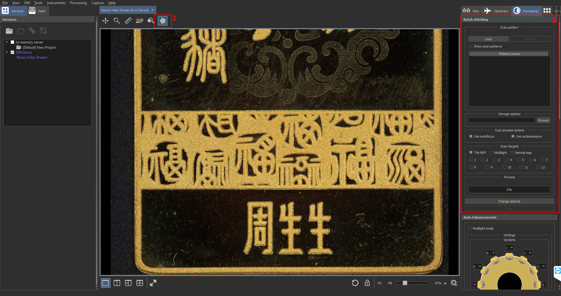
Tool allows to mark rectangle regions in XY plane and to run object scanning in selected light modes in these regions. The basic workflow is:
- Create manually batch stitching region pattern with all scanned regions. We suppose that all objects are situated in slots that does not change in size and position on the stage. So actually you need to markup each scanned slot.
- Save pattern to disk (if you want to use it again after disconnecting from microscope) and load again when you connect to the microscope again
- Use the same pattern for batch scanning changing only objects in slots.
The tool GUI consists of two parts:
- Scanning area marking tool
- Batch stitching control panel (called Panel below).
Scanning area marking tool
Using the tool it is possible to markup new areas for scanning, and select, move, delete or copy already created scanning areas.
How to create new scanning area?
- Click on marking tool icon to activate tool
- Find slot corner on videostream and click on it. A new point will be added. You have to select 4 corners of the slot step-by-step. Often all 4 points cannot be seen together on one videostream field of view. In this case you may add point, activate stage control tool (see Mouse Navigation Instrument), move stage in XY plane while you see the next corner in current field of view, then activate marking tool again and add new point (all previous added points are saved). Also for XY-movement you may use stage control GUI (see Stage Control).
- Double-click by left button of mouse to finish markup of the region (you need to add at least 4 point to do it).
- In batch stitching GUI panel you will see a new region added to the list and rectangle region becomes blue.
Scanning area selection
Click inside the region (blue rectangle) by left-button of mouse to select it. An alternative way to do it is to select the item in the list in batch stitching GUI panel.
How to delete scanning area?
- Select scanning area
- Press "Delete" on a keyboard
How to move scanning area?
- Select scanning area
- Drag and drop scanning area by left mouse button.
Copy and paste scanning area
This option is useful when objects slots have similar size, so you may markup only one slot, other scanning regions will be created by copy, paste to needed point
- Select scanning area
- Press "Ctrl+C"
- Move XY-stage to see the left-top corner of new area
- Click by right mouse button on the corner
- Press "Ctrl+V"
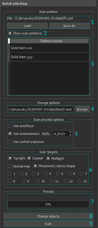
Batch stitching GUI panel
| 1. Buttons for loading / saving scanning area pattern |
2. Checkbox to show / hide scanning pattern over videostream from microscope | |
3. List of scanning areas. It supports:
| |
4. Set folder to save results of batch stitching. In this folder you will see subfolders with current scanning area names, in each subfolder results for various lightings. | |
5. Options performed before scanning in each scanning area:
| |
6. Select lighting and postprocessing modes for each object. For example, you may scan in top light and multi-light modes. | |
7. Progress-bar for batch-scanning process | |
8. Button for changing objects in slots. The stage will automatically moved from the top-light for comfortable change of objects. The names of scanned areas are changed (numbers are incremented to produce unique folder name) | |
9. Button for launching batch scanning. After launch, the caption changes to "Stop", after click on it the catch scanning will be stopped (after finishing the scan of current scanning area). |
Basic workflow for batch scanning
- If you have saved pattern you can load it from disk by "Load" button on batch stitching GUI panel, and move to step 6, otherwise - go to step 2.
- By moving XY stage find the object slot in a microscope field of view (see Mouse Navigation Instrument)
- Find optimal focus for the object (see Autofocus tool)
- Markup object slot by scanning area marking tool. By repeating steps 2-4, create pattern for object slots
- Save patter to disk by clicking "Save As" button on batch stitching GUI panel.
- Specify a folder for saving results of scanning by "Browse" button on batch stitching GUI panel.
- Tune parameters of scanning: autofocus, autoexposure, scan targets (lighting)
- Press "Scan" button. After these actions scanning will be launched. After its finishing in the folder specified on step 6 subfolders with the names of scanning areas (see list of regions in batch scanning GUI panel) will be created. In each subfolder you will see image files. In the name of the file you will see the date and time of the scanning and lighting mode used for that scan.
- After the scan is finished, press "Change objects" button.
- When the stage will stop, change objects in the slots
- Repeat steps 9-10.
Usage of cached exposure
Auto exposure process now is started on the center of the scanning area. Different scanning objects may have different central regions, while it may be necessary to scan objects with the same exposure. Panel contains option "Use cached exposure" to do so.
- At first, you need to calibrate desired exposure for "top light" and "coaxial" lightings.
- Check both "top light" and "coaxial" on "Scan targets" panel and uncheck others.
- Check "Use autoexposure" and uncheck "Use cached exposure".
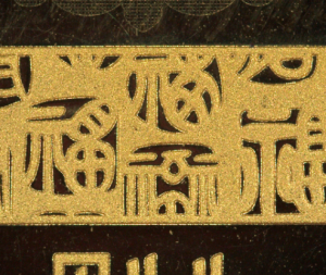
- Move XY-position to a region of the object to scan for calibration with using Mouse Navigation Instrument. For example, scanning object is a gold plate and you want to make gold texture normally exposed:
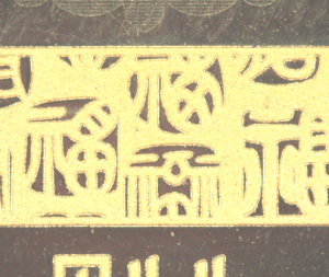
- Mark approximately central area of the picture using our marking tool:
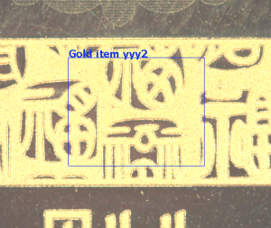
- Press "scan" button, wait and check results for calibration region exposure. For example, you may see:
- If you see overexposure or underexposure, repeat this procedure using another exposure shift setting near the "Use autoexposure" checkbox.
- Uncheck "Use autoexposure" and check "Use cached exposure". Exposure values that cached on the first step will be used for next scans. These values are stored in the program config file and will be used in future program launches.
FAQ
Why focus value may changed when I load a pattern file?
Focus value is saved in the pattern file. When you load a pattern file, the program sets the focus value from pattern to a microscope.
For now, the last opened pattern file is stored in the DM config. When the DM will be launched next time, the pattern file will be opened and all scanning areas will be loaded.
But the focus value could be different from stored in the pattern file after connecting to the microscope.
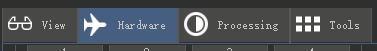
To save focus value between DM launches you should now open 'Hardware' tab on the right program panel, scroll down to the 'Motor encoder values' section and click on the 'Set as Default' button.
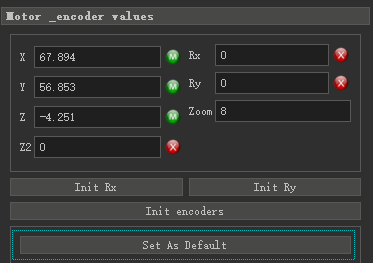
It stored current focus value and many other DM parameters in the DM config. They will be used at next DM launch.
How to save or change focus value in a pattern file?
Change focus value in the DM program, then press "Save As" on the Panel and save the pattern with new focus value.