...
| Panel | ||||||
|---|---|---|---|---|---|---|
| ||||||
|
Creating "Sandwich" Inclusions
For the stones with inclusions, the system now supports the ability to increase in some cases the mass of the solution by specifying that some part of inclusion can be included in the future solution. This can be done by marking an inclusion as multi-part ("Sandwich").
...
| Include Page | ||||
|---|---|---|---|---|
|
Scanning - Applying Facet Marking from Sample
Now during scanning using a loaded sample cutting, a facet marking from this sample is automatically transferred to the created 3D model. This provides an effective way of getting the correct facet classification (marking) for your model and creating the appropriate reports .
...
- You can view the facet marking of your sample (DMC format). Do one of the following:
- As you select your sample in Cutting & Method, it is added to the Models section. There click its name, then on the right panel, click Facet Marking.
- Open your DMC in HP Carbon and then click the Facet Marking button on the right panel. The file can be opened by:
- Drag and drop your DMC to the HP Carbon window.
- In HP Carbon, select File > Open, navigate to your folder, then start typing the name of your file. As soon as it is suggested, select the file and click Open.
- You can change something in the facet marking of your DMC sample. To do this, perform the steps:
- Open DMC and its facet marking as described above.
- Make changes to the facet marking.
- Click Export Sample, specify a name for your changes version, and then click Save.
- Add a new version of the sample to the system, remove the old one.
Industrial Object Models - Build and Facet Marking Improvement
A building of industrial object models (cubes, cuboids, trapezoids, truncated cylinders) is improved.
...
- Prepare your DMC sample with the appropriate facet marking.
- Use the Scan mode.
- In the Cutting & Method section, add
 your sample to the list.
 - Select your sample as a cutting. The system will automatically set the optimal method.
- Start scanning.
The model of your object is built using one of the improved methods and added to the Models section. Its facet marking is automatically taken from your sample.
Trapezoid Workflow
Now you can use the system to quickly obtain important information ( report ) about your trapezoid-like objects:
...
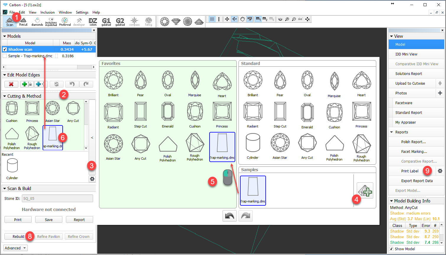
- Use the Scan mode.
- Use the Cutting & Method section.
- Expand the section.
- Add your sample.
- If necessary, drag your sample to the Favorites list.
- Select your sample to be used as cutting. The sample will be added to the Models section.
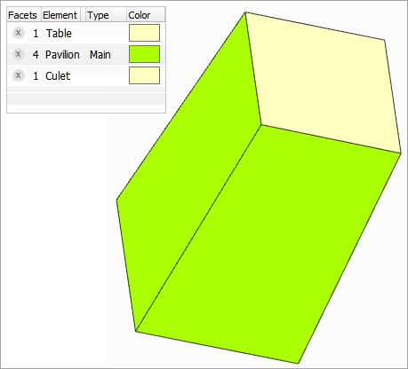
- To check the facet marking of your sample, in the Models section, click your sample, then on the right panel, click Facet Marking.
- Side facets of your trapezoid should be marked as "Pavilion - Main".
- If you want to modify the facet marking of your sample, in the Facet Marking dialog make your changes, then click Export Sample and save as DMC.
- You will need to add a changed version of the sample and then use it (repeat step 2).
- Remove the old sample from the Samples list.
- Run Scan or Rebuild. Your new scan is added to the Models section.
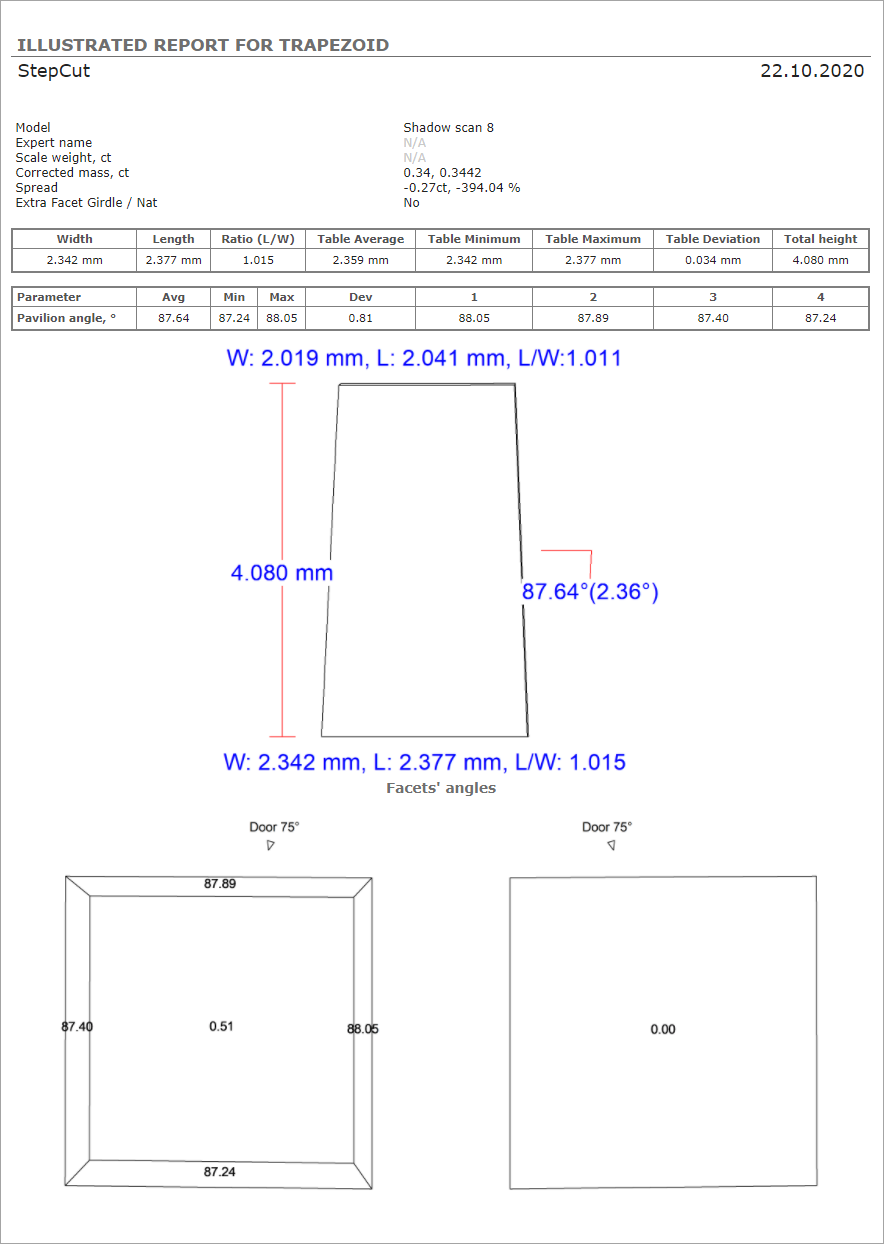
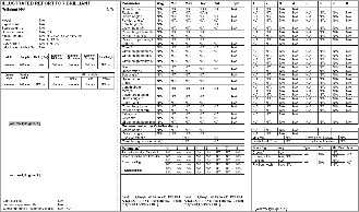
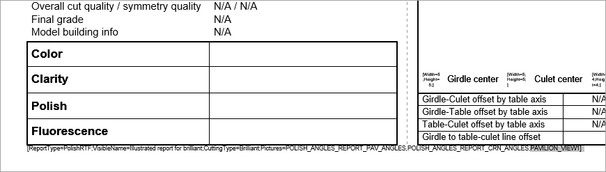
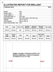
With your new scan selected, on the right panel, click Polish Report, go to Open HTML, then select "Illustrated report for trapezoid" and Make Report.
Expand title Show report dialog and result... 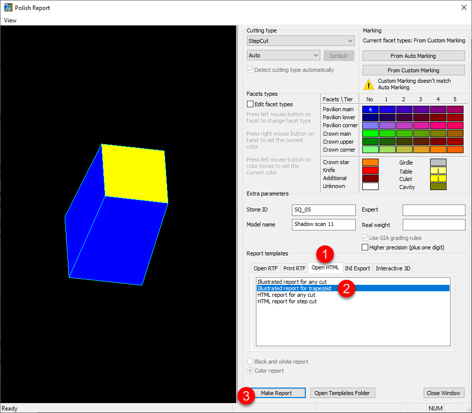
Polish Report Templates
HTML Illustrated for Trapezoid
The new template for Polish Report is added - HTML Illustrated for Trapezoid.
...
This template is an essential part of the Trapezoid Workflow.
Square Cushion - Cutting Type Support and Reports
Now in Polish Report, the Cutting Type list includes "Square Cushion".
...
Also, the Standard Report for Square Cushion is updated correspondingly.
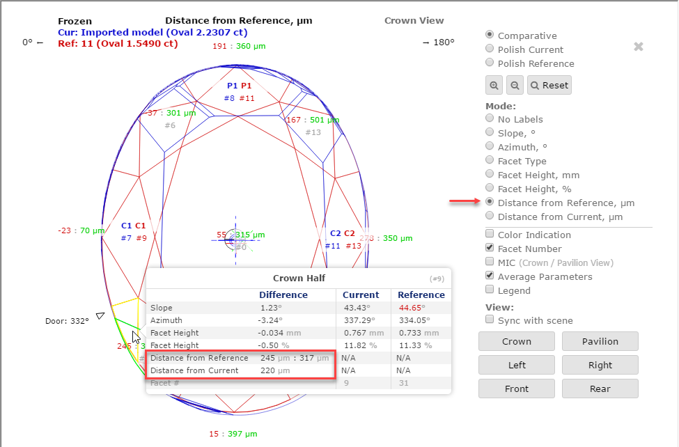
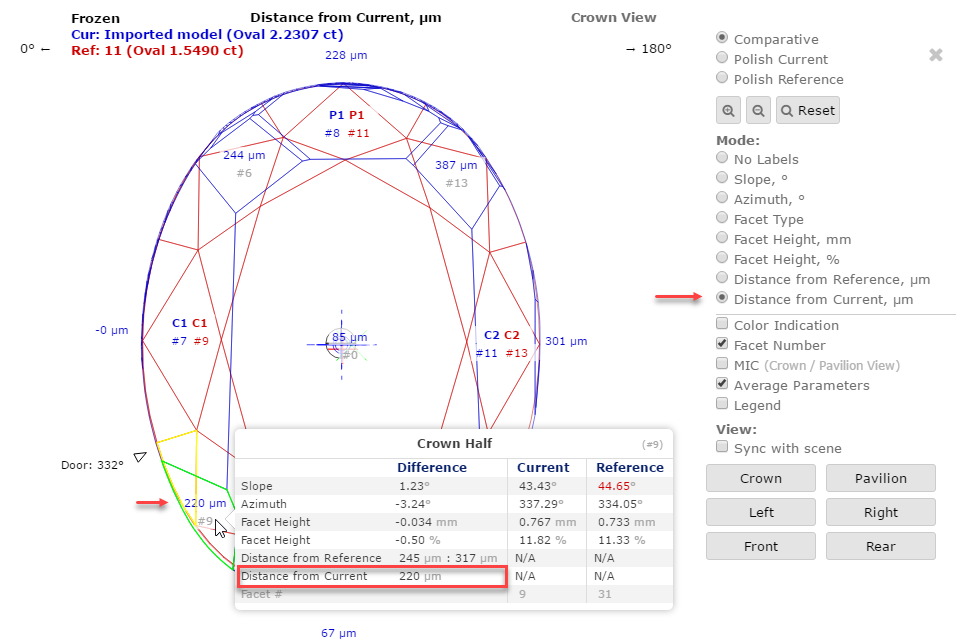
Comparative I3D Mini View - Distance from Reference/Current
For the Comparative I3D Mini View, two new modes are added:
...
Distance from Reference, µm | Distance from Current, µm |
|---|---|
|
|
|
|
Notes on meaning: | |
|
|
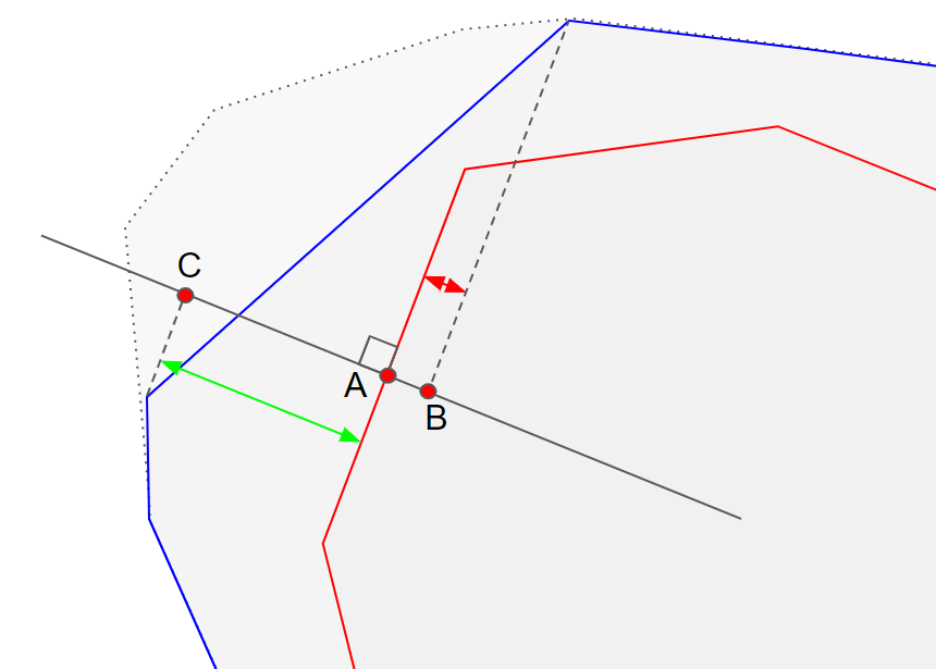
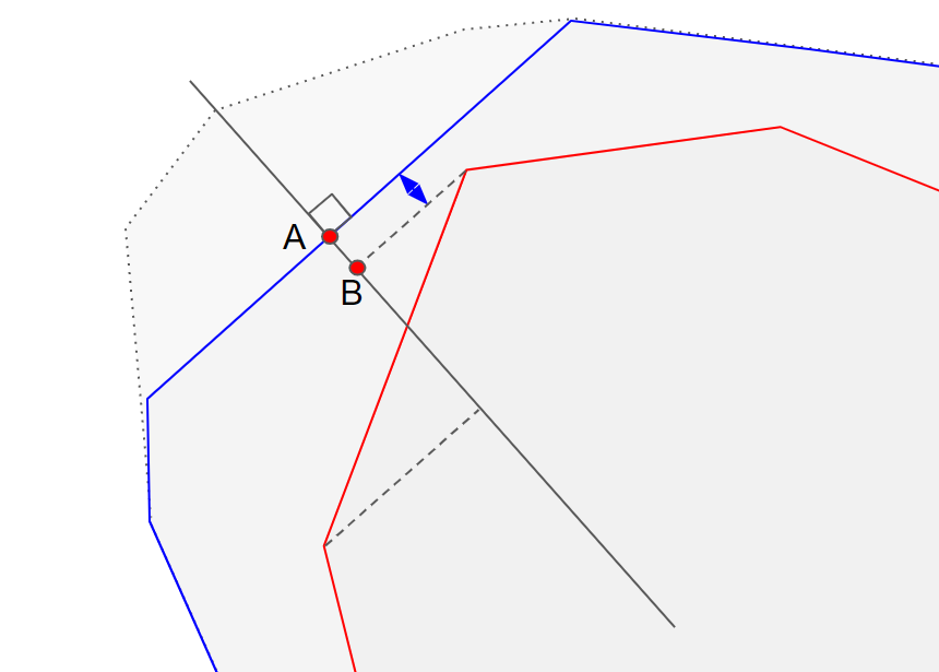
Here is an example:
New Smart Recut Parameters
The new parameter is added to the appraisers used by the Smart Recut algorithms.
SquareDeviation Tolerance
| Info |
|---|
| This parameter is applicable to the following cuts: AnyCut. |
...
| Value | Units | Bookmark | Tab | Parameter Name | Comment |
|---|---|---|---|---|---|
| Avg (the only value) | None | NA | Cut | SquareDeviationTolerance | Visible only when presets are displayed. |
G1 Galahad
New Features
For the G1 Galahad mode, the new features were added. As this functionality is shared with the Galahad Compass product, see details in the Galahad Compass documentation:
...
- Workflow improvements
Actual Cut and 4 Colors for Steps
Order of Work - Stages and Steps
Actual Cut Model
Protection of Overcut Area ("lock" icon)
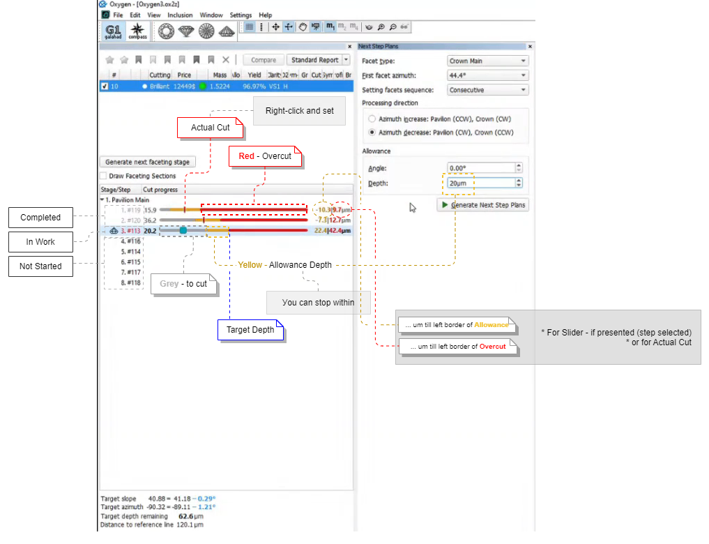
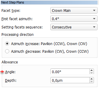
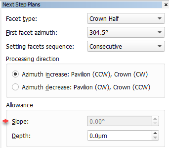
Slope Allowance Parameter
In the Next Step Plans panel, the Allowance section, the Angle parameter is renamed to Slope. The usage of the parameter is temporarily blocked (next step calculation does not consider this parameter) due to technical reasons (planned to be restored in the upcoming releases).
| Was | Now |
|---|---|
|
|
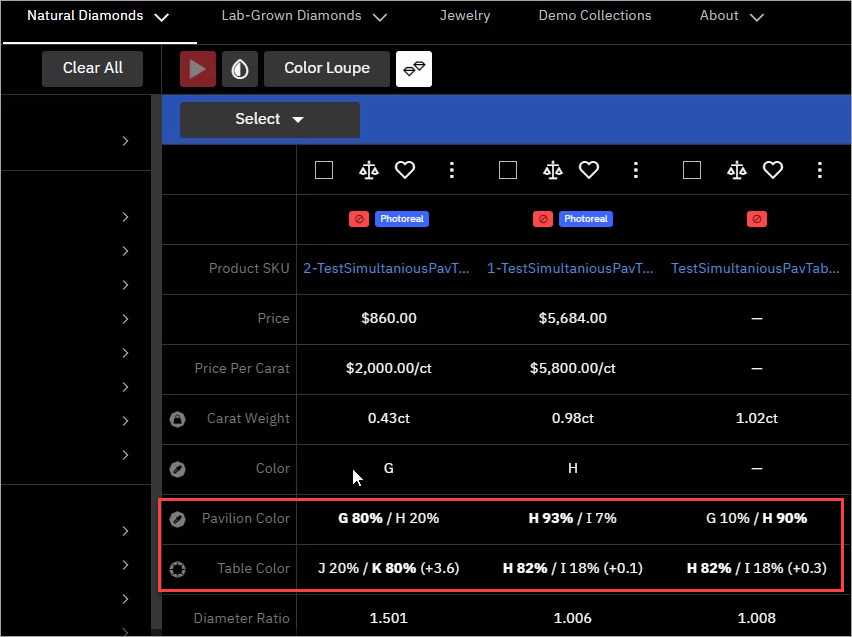
DZ Color Estimation - New Approach and Progress Bar
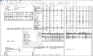
Previously for DZ Color Estimation , the calculation of Table Color was performed after the Pavilion Color for all the solutions - the process could take time but the progress was not anyhow displayed within the system. This caused the cases when the export to Cutwise could have been started before the calculation is finished thus the data uploaded to Cutwise did not contain the Table Color information. Now the Pavilion Color and Table Color are calculated together for each solution and the entire progress is indicated:
...
This approach guarantees that during export to Cutwise all the solutions will be exported with information about both Pavilion and Table Colors.
Polish RTF Reports - Views without Invisible Edges with Rotation
In the Polish RTF Full Report, there are Pavilion and Crown views without indication of invisible edges (PAVILION_VIEW and CROWN_VIEW bookmarks):
...
| Expand | ||||||||||||||
|---|---|---|---|---|---|---|---|---|---|---|---|---|---|---|
| ||||||||||||||
|
Cutwise Integration - Upload to Cutwise vs Manual
When using Integration with Cutwise, you have two ways of uploading your data to Cutwise:
...
It is important to remember, that if you use the Upload to Cutwise function in HP Carbon, you should not use the manual approach for the same data, because after Upload to Cutwise is used if you try to manually upload the same models/reports, you will not see the new data in Cutwise - the one previously uploaded from the system with the Upload to Cutwise function will stay unchanged.
New Logo and Icons
HP Carbon now has the new logo:

And icons: 

Fixed Problems and Improvements
The following fixes for the known problems and improvements are implemented:
...