...
| Panel | ||||||
|---|---|---|---|---|---|---|
| ||||||
|
Public Features
The functionality described in this section is available to users.
Boundary Plane Tool
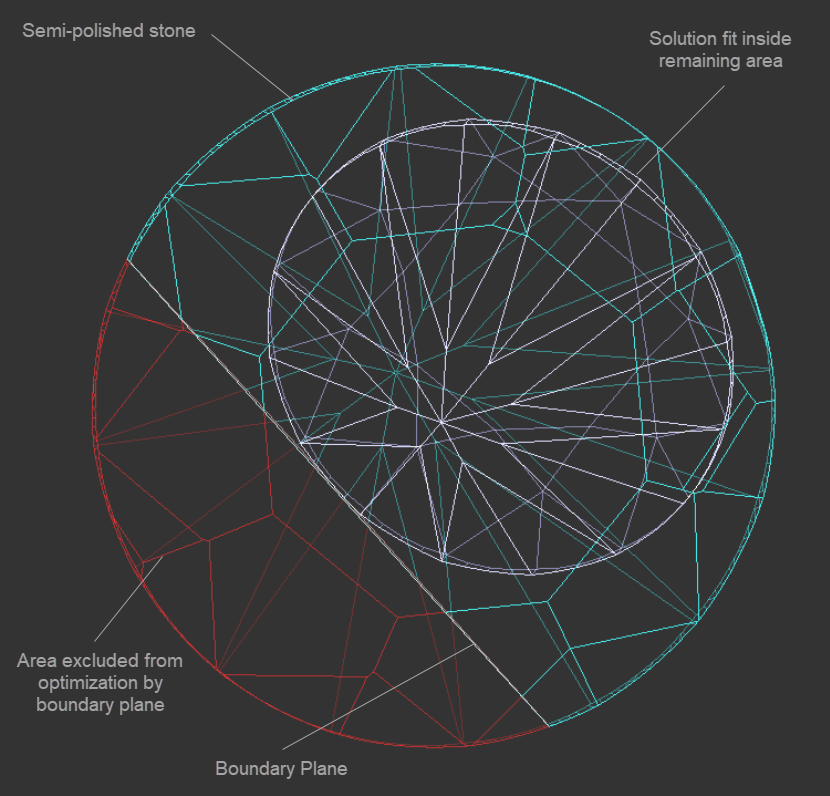
Now you can add boundary planes to exclude some parts of the stone from the optimization.
...
The Boundary Plane Tool allows placing the plane which virtually cuts off the part of the semi-polished stone to exclude this part from optimization.
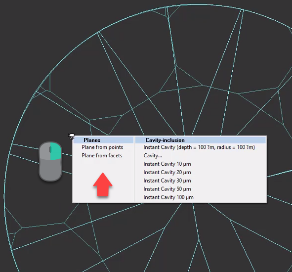
To add a new boundary plane, in the Scene, right-click the model, in the displayed context menu, in the Planes section, select one of the options:
- Plane from points
- Plane from facets
Plane from points
A new boundary plane can be plotted via specifying the set of points on the stone surface through which the plane should pass.
...
- The first click sets the vertical plane normal to the screen
- The second click changes the direction of the plane
- More clicks add additional points and set the plane closest to all the points added
As soon as you set the plane, you may set the offset depth, then apply the changes.
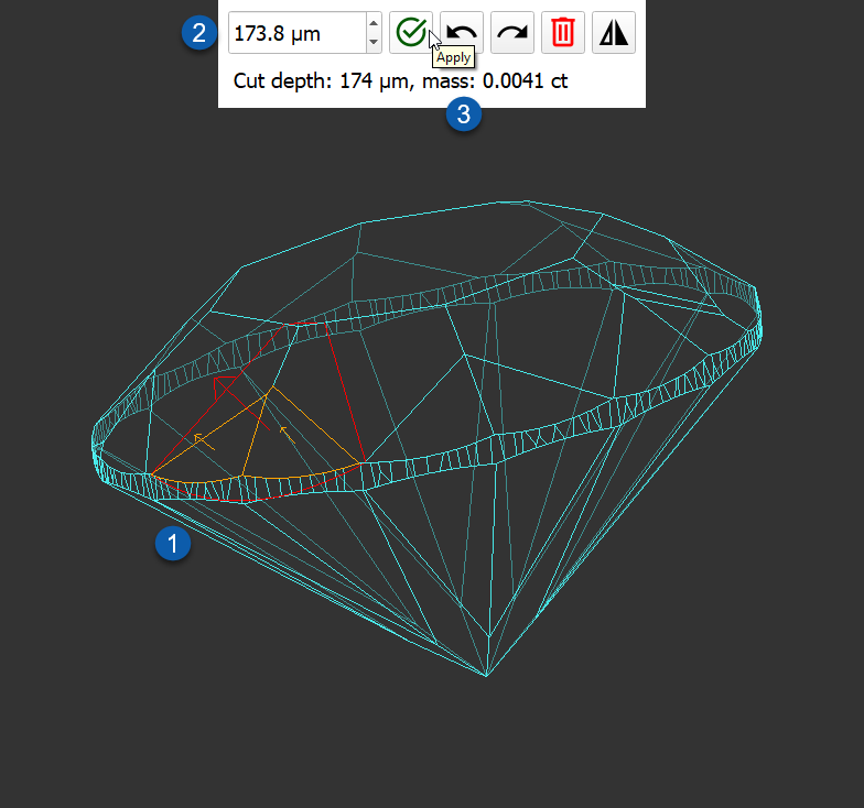
Plane from facets
When using this option, you need to select the facets which will be used to calculate the combined facet (1), then set the offset depth (2), then apply the changes (3).
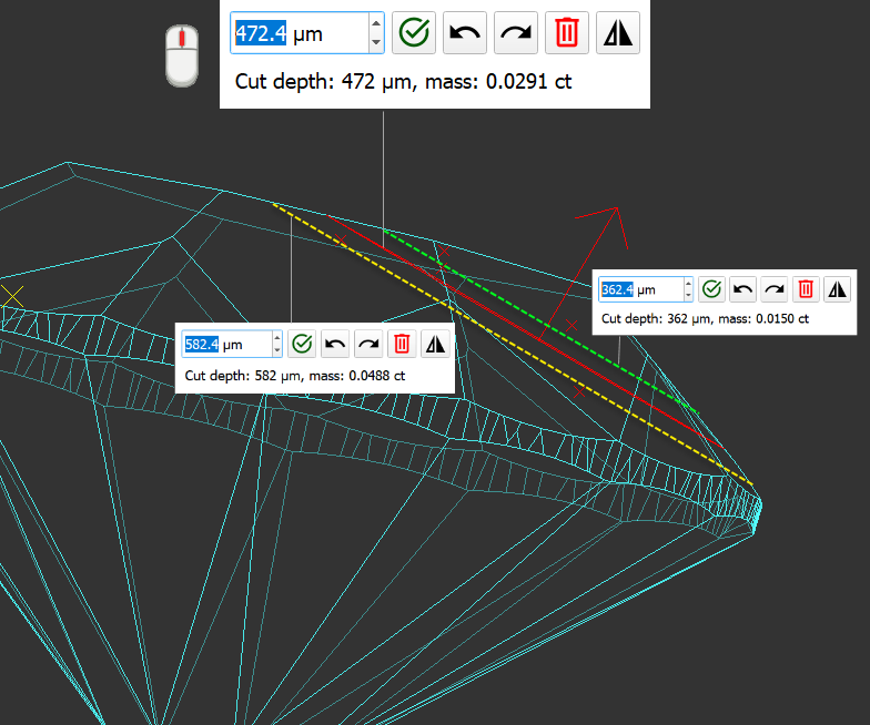
Offset Depth
Whether you create a boundary plane from points or from facets, after creating the plane, you can increase on decrease its depth by specifying the offset.
| Info |
|---|
You can type in the offset depth directly or use arrows or scroll the mouse button. |
Editing Planes
You can create several boundary planes one by one. Any created plane can be edited or deleted at any moment. To edit the specified planes, in the Scene, right-click the model, in the displayed context menu, in the Planes section, select Edit planes. Select the plane, then edit it by:
...
To delete the plane, click  .
.
"MyRound | GIA Facetware + MyRound" Appraiser
Changes in Profiles
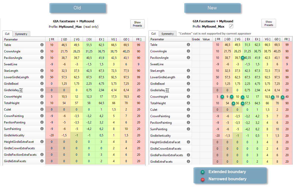
New Limits for "MyRound_Max" Profile
For the "MyRound_Max" profile of the "MyRound | GIA Facetware + MyRound" appraiser, new intervals for some parameters have been set.
...
- Pavilion Angle
- Crown Height
- Total Height
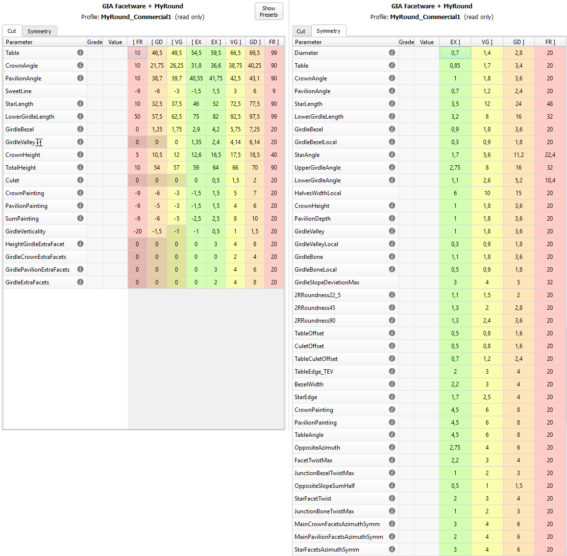
New Profile - "MyRound_Commercial"
For the "MyRound | GIA Facetware + MyRound" appraiser, the new "MyRound_Commercial" profile has been added. This profile parameter ranges statistically match the brilliants produced by the large manufacturer.
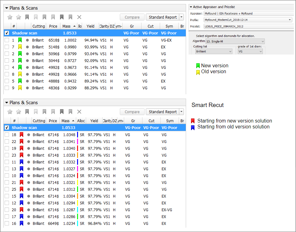
Improved Functioning for Larger Mass for VG Grades
Basing on examples from the clients, improvements have been implemented for the “MyRound | GIA Facetware + MyRound”. The implemented changes provide for the appraiser the ability to effectively interact with the complex set of parameters from GIA Facetware that have the VG grade there and as a result, the appraiser allows finding VG solutions with the larger mass.
Smart Recut with "Fix" Options - Remove Facets from Fixing
A new Element Multi Selection Tool can now be used with the "13. SmartRecut (Brilliant, Oval)" algorithm. Using the tool, you can adjust the Fix Girdle, Fix Crown, Fix Pavilion options usage by manual removing the facets from fixing. For example, if under the "13. SmartRecut (Brilliant, Oval)" algorithm, the Fix Girdle option is selected, it freezes all the facets of the girdle not allowing the algorithm to remove them; then, using the Element Multi Selection Tool you can exclude some facets from this freeze, so that the algorithm will mandatorily remove them from the future solution.
...
To use the tool, in the Recut mode select your convex scan in the list, then select the "13. SmartRecut (Brilliant, Oval)" algorithm, set "Fix" options, and then on the main panel toolbox, click  > Remove facets from fixing. This activates the Element Multi Selection Tool; now in the Scene, you can mark facets to be removed from fixing.
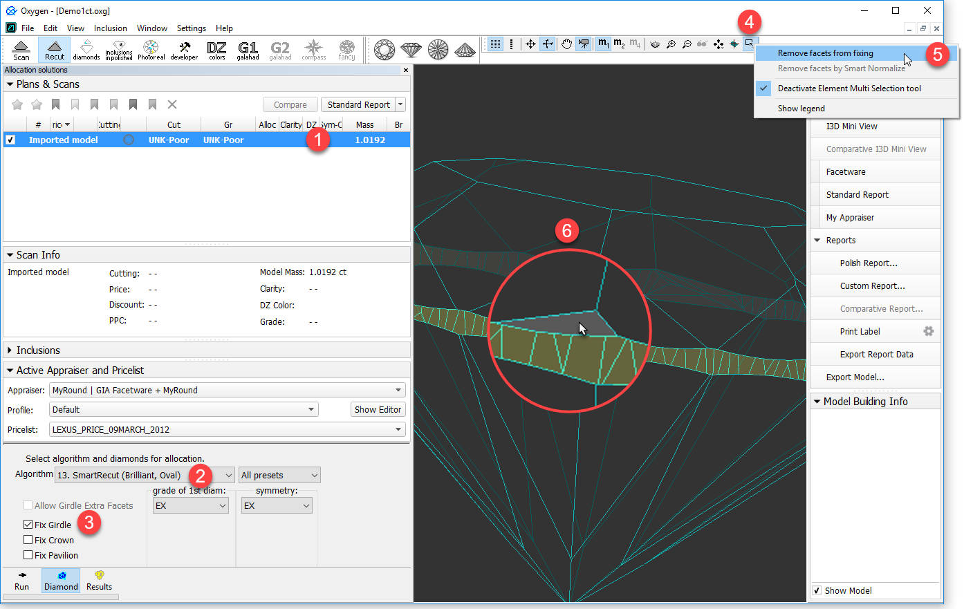
The Element Multi Selection Tool includes legend available on clicking Show legend.
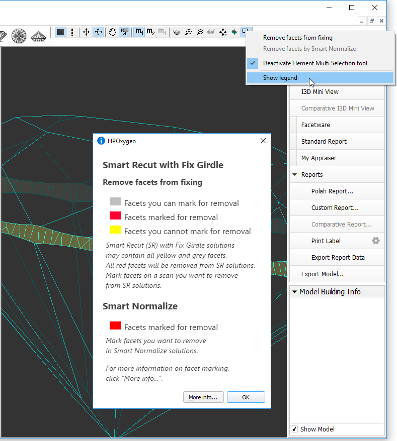
To view additional information, click More info. This will open a help page in your browser containing some detailed information on functionality.
...
| Info |
|---|
Note that highlighting of current fixing options is only visible in the Scene when the "13. SmartRecut (Brilliant, Oval)" algorithm is selected and fixing options are enabled. |
Interface - Configurable Set of Columns in Solution List
The set of displayed columns for the scan/solution list is now configurable: you can select columns to be displayed/hidden and also change their order. The function is available for:
- The
 mode, the Plans & Scans section.
 The
 mode, the Models section.
Info title Notes: - The configuration for each mode is performed and stored separately.
- The configuration is not available in the Lock to Scan mode.
 To customize columns, right-click the name of any column, then in the context menu select/clear checkboxes for your columns. For advanced configuration (several columns at once, change order), in the context menu, click Details. The Adjust columns dialog is displayed. Here you can select/deselect several columns at once and change their order by drag-and-drop.
...
| Info | |||||
|---|---|---|---|---|---|
Note that for the Multiple Diamonds in One Solution mode, the Adjust columns dialog differs: you can customize both solution and diamonds columns.
|
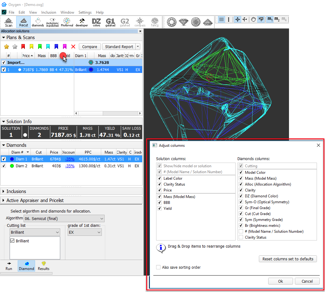
To restore the default set of columns in the default order, click Reset columns set to defaults.
...
| Also save sorting order | |
|---|---|
| Selected | Not Selected |
Sorting you use when closing the current project will be used for the next project you open. Note Once selected, the option stays active in spite of restarting the program or opening the next projects. | For the next project you open, its own saved sorting will be used. Notes
|
Generating Reports - New Paths and Naming
For some reports, the paths for storing generated report files and file naming has been changed:
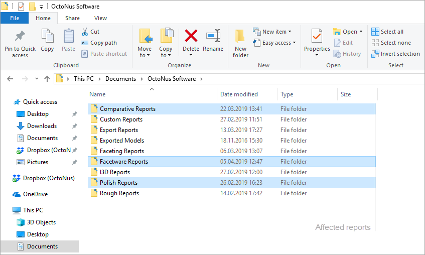
The new paths and file names are the following:
...
| Expand | ||
|---|---|---|
| ||
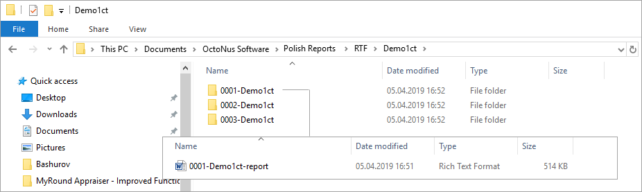
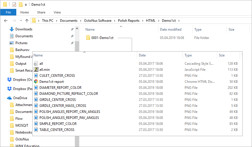
Polish Reports. Now when you click on the right panel, the Polish Report, then, in the Report templates section,
For example, if you run Polish report 3 times for the "Demo1ct.oxgz", you will obtain:
|
Scene Model and Photos View - Show Grid Option
Now for the Scene in Model or Photos view, you can show the grid. To enable the grid, set Scene to the Model or Photos view, then from the main menu, select View > Show Grid. To disable the grid, clear the Show Grid checkbox. As you zoom in/out, the grid step and units (mkm, mm) adjust to the current zoom level.
With the grid enabled, you can click  to display vertical and horizontal measurements (mm) of the projection of the displayed model in its current position.
Click  again to hide measurements
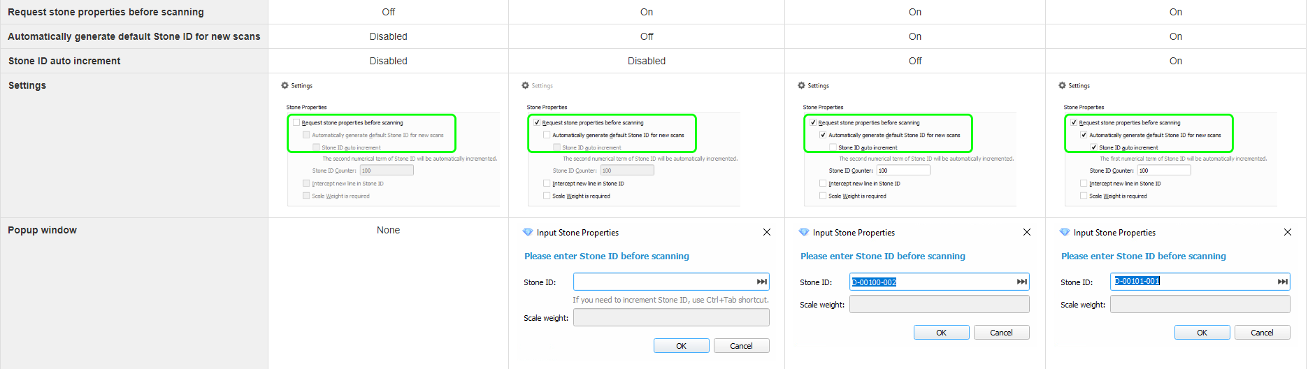
Input Stone Properties - Changes in Dialog
During scanning, on clicking the Shadow scan button, the Input Stone Properties dialog may be displayed.
...
- The hint text for keyboard shortcut CTRL-TAB has been changed:
- Was : "Use Ctrl+Tab shortcut to increment Stone ID"
- Now : "If you need to increment Stone ID, use Ctrl+Tab shortcut"
- The hint:
- Was : always displayed
Now : hidden when the Automatically generate default Stone ID for new scans option is selected.
Info Only the hint is hidden - the Ctrl-Tab combination still can be used.
Fixed Problems and Improvements
The following fixes for the known problems and improvements have been implemented:
...