Introduction
In this release we introduce an improved autoplotting algorithm that addresses the problem of deep subsurface inclusions and thick cracks. The average deepness of subsurface markings and point subsurface inclusions was reduced. As for the cracks it is the first release where we are announcing the automatic and semi-automatic plotting of flat cracks. The crack autoplotting works well on standalone non-transparent flat cracks. The result of crack processing is a 20-microns thick flat crack that can be manually edited. Also from this release we support a photorealistic rendering of cracks in planned diamonds. This feature helps to estimate the influence of some crack on visual appearance of the diamond during planning.
Subsurface inclusion processing improvement: reducing the deepness
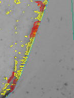
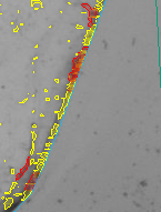
In previous release of autoplotting program there was a problem with allocation of subsurface marking and small subsurface inclusions. Most of them were too deepened inside the rough. You can see such a problem on the left picture below (problem zones are near the blue line of rough contour). On the right picture you can see the result of new release program where the average deepness of subsurface inclusion was reduced.
Please do not forget to use the QC-tool for removing subsurface inclusions. From this moment the average deepness of subsurface inclusions was reduced (now it is less then 150-200 microns). So the classification of inclusions into subsurface and not-subsurface has become simpler.
Flat crack autoplotting
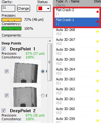
This is the first release where we represent the algorithm for autoplotting flat cracks. When the process of autoplotting is finished you may see autoplotted flat cracks in the list of inclusions:
The new algorithm is tuned for automatic allocation of cracks that are:
- flat (if the crack is curved - the crack will be plotted as a simple Auto3D inclusion)
- standalone (there are no other inclusions near this crack)
- non-transparent (for transparent inclusions the algorithm may plot flat crack with wrong profile or it will remain a Auto3D inclusion)
The autoplotted flat crack is 20-microns thick. The auto flat crack object is identical to manual one. So you may edit it as a manual flat crack (you may read more about flat crack editing in the next chapters of this documentation).
Semi-automatic flat cracks
The new autoplotting algorithm may plot a small percent of real flat cracks and some of flat cracks will be presented in autoplotting results as Auto3D inclusions. For such real flat cracks you may try to automatically convert Auto3D to flat crack.
To do this you should to:
- Select this Auto3D inclusion by inclusion selector.
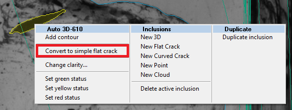
- Right-click on this inclusion
- Choose a menu "Convert to simple flat crack" in Auto 3D-<inclusion number> section
After this the Auto3D inclusion will be converted into flat crack.
NOTE: For some Auto3D inclusions the convertion to flat crack is impossible (for example, if crack is not standalone). In this case you will not be able to see "Convert to simple flat crack" in Auto 3D-<inclusion number> section at all. For such inclusions you cannot allocate flat crack automatically - plot it manually and delete the old Auto-3D inclusion manually.
Rolling back the convertion to flat crack
In some cases the autoplotting algorithm or semi-automatic convertion process may make some mistakes. For example, the resulting flat crack has invalid plane or profile. In this case you may roll-back the convertion to flat crack executing the following steps:
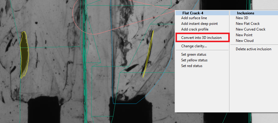
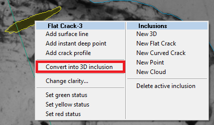
- Select this Flat Crack inclusion by inclusion selector.
- Right-click on this crack
- Choose a menu "Convert into 3D inclusion" in Flat Crack-<inclusion number> section
Below you can see the example of bad convertion to flat crack (after semi-automatic convertion to flat crack - this flat crack was not allocated automatically). In fact this inclusion is a curved crack - that is why it has a wrong plane:
NOTE: After convertion of flat crack to 3D inclusion you may see the thick inclusion (maybe up to 200-300 micron thick). It is normal. In case if this inclusion is a flat crack and the thickness of Auto3D inclusion is too big you have to plot a flat crack manually.
Editing autoplotted flat cracks
It was already mention in this document that autoplotted flat crack object is similar to manual flat crack object. That means that you may manually edit autoplotted flat crack.
Among possible cases where you may edit auto flat crack manually are:
- wrong crack profile because of its non-transparency
- wrong crack profile because of some growths on the crack (for example, because of inclusions near the crack)
- wrong estimated plane of flat crack
In this cases you may manually edit inclusion editing its profile and deep points
Features:
- Improved subsurface inclusions processing
- Automatic crack processing (1-st version). Only flat cracks are supported.
- inclusions classification into cracks and not cracks
- crack plane estimation
- Semi-automatic 3d inclusion into flat crack conversion
- menu item for conversion of 3d inclusion into flat crack and back for the inclusions that seem to be a crack
- ability to roll-back the automatic crack with the same menu
- menu item for conversion of 3d inclusion into flat crack and back for the inclusions that seem to be a crack
- Crack material reconstruction and rendering
- crack material reconstruction after first switching to Photoreal mode and active diamond selection (takes a little while, no progress bar). The solution has to be already allocated and HIG photos should be loaded.
- crack visualization inside active brilliant (in Photoreal view)
- crack material reconstruction after first switching to Photoreal mode and active diamond selection (takes a little while, no progress bar). The solution has to be already allocated and HIG photos should be loaded.
Known issues:
- After changing the segmentation threshold to some another and back the cracks are not saved, all inclusions become 3d
- Converting inclusion to crack and back can take a long time if there are many inclusions plotted (over 1000)
- Auto-plot from time to time crash on some projects