Here you can find information about what is new in HP Carbon version 1.9.2.
Smart Cuts. Updates
Special Appraisers for Smart Cuts
Video summary: The High Performance profile prioritizes Performance over Yield, and produces solutions with high Optical Performance and symmetry, by limiting the Sweet Line and Generic Smart Cut Parameters. The Commercial profile is an optimal balance between Performance and Yield. The Max Mass profile prioritizes Yield, and gives maximum mass solutions. The client can choose one of these plug and play profiles, depending on required Performance and Yield ratio, run the optimization, and get good results right away. Video keywords: Smart Cuts, High Performance profile, Commercial profile, Max Mass profile, Performance/Yield ratio Data As Separate Page | On YouTube | SpecificationVideo | Special profiles of appraiser for Smart Cuts Published: 2023, April 04 Last Updated: 2023, April 04 v.2.0 Published in: Release Notes Documentation NA Playlists NA Also
Plug-and-play appraiser for Emerald 3x4 Smart Cut
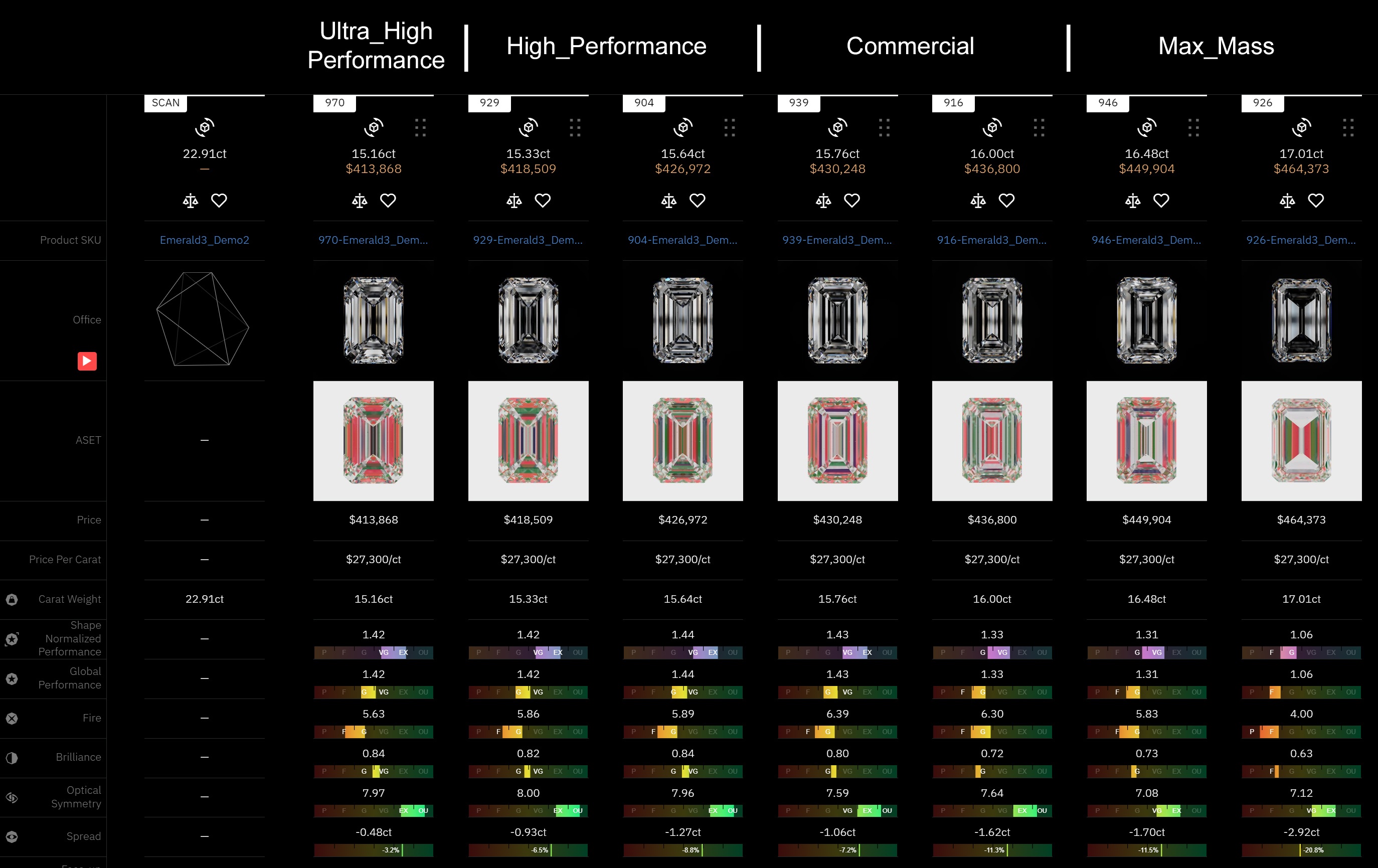
Profiles of appraiser for Emerald 3x4 Smart Cut were updated.
There are 4 non-editable pre-configured plug-and-play profiles:
- Ultra_High_Performance
- High_performance
- Commercial
- Max_Mass
And two user profiles:
- User_Profile1
- User_Profile2
Pre-configured profiles are designed to give users a fast start with the allocation and consider the user’s needs. Three profiles are required to grant the user the desired range of options:
- Ultra_High_Performance profile limits the parameter range to achieve high performance and symmetry with yield compromise.
- High_Performance profile uses a wider parameter range but still gives solutions with high performance and symmetry.
- Commercial profile gives balanced performance and yield.
- Max_Mass profile is designed to give high-yield solutions but can sacrifice Optical performance.
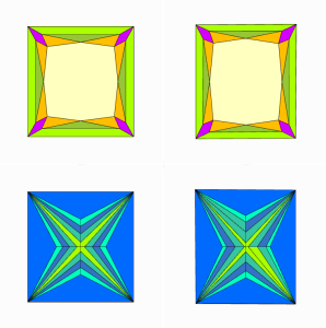
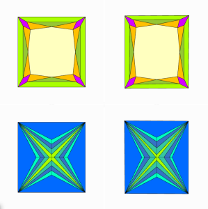
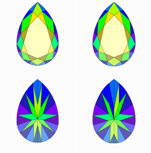
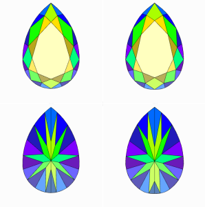
Solutions created with pre-configured Profiles are shown in the Cutwise Project:
Users can select one of the pre-configured profiles and immediately go to the allocation procedure without laborious Profiles modification.
For users that want to manually adjust Profiles – Pre-configured profiles can be a good starting point for modification. Users can copy Parameters from pre-configured profiles to one of the editable profiles User_Profile1 or User_Profile2 and then modify desired Parameters (for instance, Total depth, Table or Crown/Pavilion Main facets Slopes limits) as per Factory requirements.
IMPORTANT NOTE
If you already use version 1.7.X and newer, then note:
Current 1.9.2 version doesn't replace existing appraiser Emerald 3X4. Thus for replacement it is required to delete folder Emerald_3x4 from C:\ProgramData\OctoNus Software\CommonData\Cuttings before installation of new version 1.9.2.
Algorithms of allocation
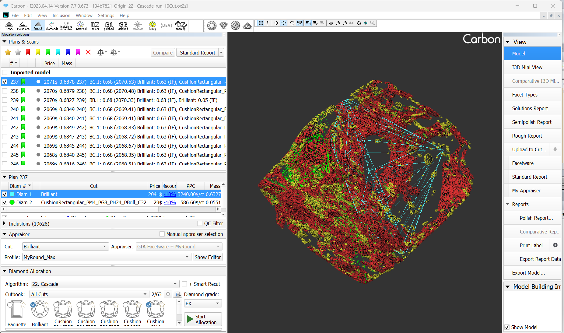
New Algorithm - 22. Cascade
An algorithm 22. Cascade is available to allocate the solutions with two diamonds. Unlike its predecessor 13. Cascade-2M, the new algorithm remains operable for cases where 5-10 different cuts are launched simultaneously and the number of inclusions in rough model exceeds 20,000-30,000 pieces.
To use the new algorithm is to select 22. Cascade from algorithm list, check necessary cuts and press Start allocation.
MESM for blocking algorithm updates
Video summary: Video keywords: MESM, blocking, algorithm description, presets, updates Data As Separate Page | On YouTube | SpecificationVideo | MESM for blocking Published: 2023, April 14 Last Updated: 2023, April 14 v.3.0 Published in: Release Notes Documentation NA Playlists NA Also
- The "MESM for blocking" algorithm have learned to work with non-convex cuts, including cuts with many grooves.
- If an input model for algorithm "MESM for blocking" is highly non-symmetric, then the algorithm may find wrong pairs of symmetrical facets. That is why sometimes the algorithm could not find an absolutely symmetric solution in previous versions of HP Carbon. It gave an error as cube solutions not selected cut. Now the algorithm run a fallback scenario in given situations. During the fallback scenario the symmetry tends to be absolute, but absolute symmetry is not mandatory.
- The "MESM for blocking" solutions name contains number of reference facets.
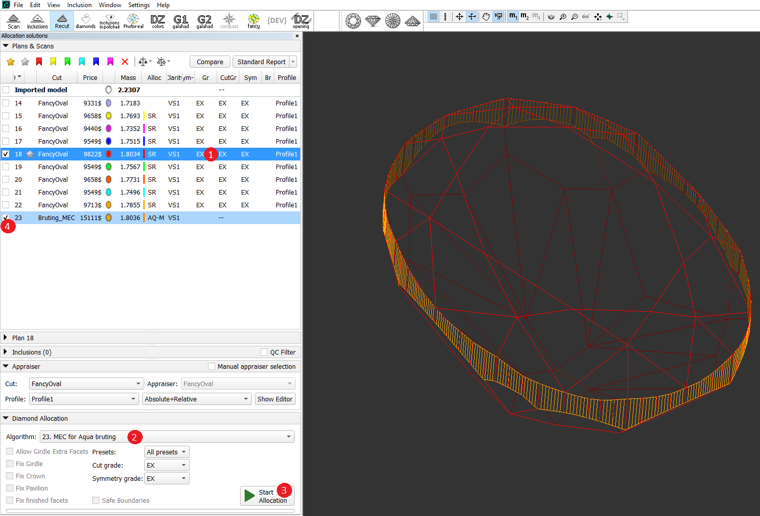
New Algorithm - MEC for Aqua Bruting
A diamond bruting machine produce a vertical smooth girdle. But the allocation algorithms solution girdle is faceted. Bruting machine operator must see in the program what result he will get in reality. That is why HP Carbon needs to find a smooth cylinder circumscribed around a selected solution. This is now can be done by a new algorithm - "23. MEC for Aqua bruting". "MEC for Aqua bruting" is applicable for any cuts
Smart Recut solutions for "Brilliant" cut has non-vertical girdle. "MEC for Aqua bruting" can cut off a bit the vertices of such solution which can lead to a worse grade. We will fix it in the next HPCarbon version. For now use "MEC for round bruting" in "Brilliant" workflow
"MEC" in "MEC for Aqua bruting" means Minimum Enclosing Curve. "MEC for Aqua bruting" solution is fully inside scan. Smooth cylinder can cross the scan, then you get knives.

To use the algorithm, first allocate your solutions via Recut > Smart Recut, then:
- Select the solution.
- Select Algorithm "23. MEC for Aqua bruting".
- Run allocation. As allocation is finished, in the solution list, the new model representing a bruting radius is displayed.
- In the solution list, select this solution.
- From the main menu, select File > Export > MME for EOS bruting... or For laser bruting... Set name and location for your model file.
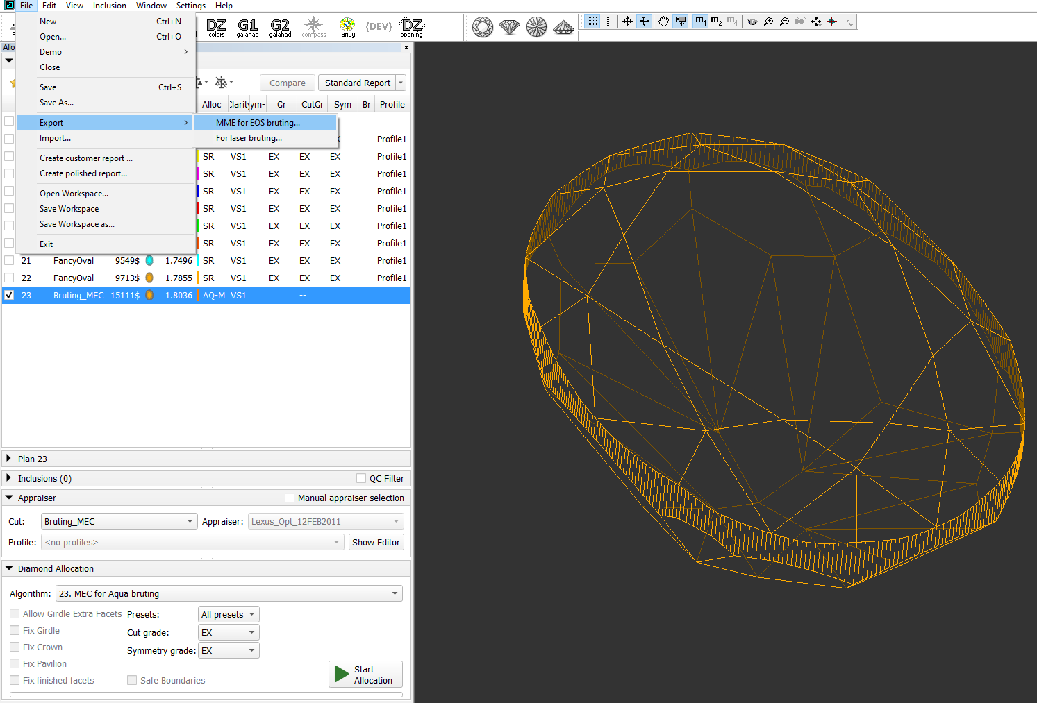
- In your bruting software, use the created file.
Reports improvements
New features for Remaining Depth mode in Comparative I3D Reports
In the previous version of Reports, the Remaining Depth mode lacked sufficient visual information to accurately track changes in deviation from the reference model across the entire girdle during the bruting process.
Fortunately, with the release of version 1.9.1 of Comparative I3D Reports, several valuable enhancements have been introduced to address this limitation:
Chart Representation: The new version incorporates a chart in the Remaining Depth mode, visually illustrating the minimum and maximum deviation from the reference model by azimuth along the girdle.
This chart provides a clear representation of deviation changes and their distribution. The horizontal axis represents the azimuth angle, ranging from 0 to 360 degrees along the girdle, while the vertical axis represents deviation values, ranging from -75 to 150 microns.
The maximum depth is visually represented by a vivid horizontal green line , while the minimum depth is indicated by a vivid horizontal red line. Color-coded tick marks are used to emphasize the precise azimuths where these depths occur.
Additionally, there are semi-transparent green and red horizontal lines that denote positive and negative average deviations, respectively, from the reference model's girdle. These semi-transparent lines are positioned between the vivid horizontal lines that illustrate extreme depths.
The average negative depth indicates overcutting of the girdle, while the average positive depth suggests that the girdle is not completely cut off.
For better correlation between a chart and its corresponding 3D model, the door's location is explicitly marked on the plot.The legend for the lines displayed on the chart  the maximum depth
 the maximum depth by azimuth
 a positive average deviation from the reference model's girdle
  a negative average deviation from the reference model's girdle
 the minimum depth by azimuth
 the minimum depth
- Girdle Markers: To facilitate the identification of areas with significant deviation, markers have been implemented on the girdle to indicate the minimum and maximum depths. These markers serve as reference points, enhancing the ability to track deviations accurately.
When the camera's inclination towards the table resides within the ranges of 0-45 or 135-180 degrees, the minimum (red) and maximum (green) labels appear as colored circles next to the girdle, each supplemented with its corresponding deviation value. Yet, when the camera's angle falls within the 45-135 degrees range, these markers adapt, transitioning from a circle to a cross. - Depth Information: Comparative I3D Reports now provide comprehensive information on the minimum, maximum, and average negative and positive depths.
These depth metrics offer valuable insights into the bruting process, empowering users to analyze and understand the extent of deviation. - Color Palette Enhancement: The color palette for the Remaining Depth mode has been repositioned, improving accessibility and enabling users to easily differentiate between various deviation values.
Overall, these updates significantly enhance visualization and provide more comprehensive information for analyzing deviation during the bruting process along the girdle. Users can now track changes with greater accuracy, identify areas of concern more easily, and make well-informed decisions based on the detailed data provided by the enhanced Comparative I3D Reports.

Trapezoid cut - Length and Width calculation
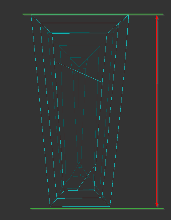
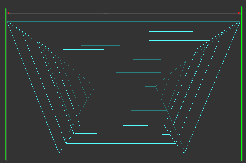
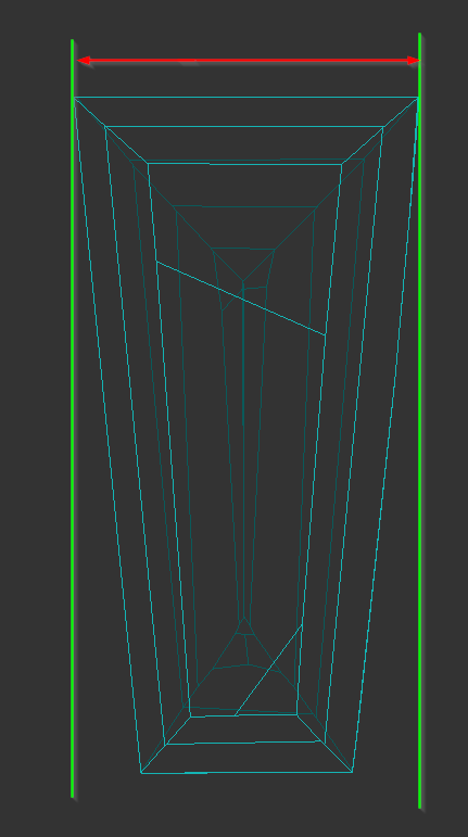
We have changed model orientation in report and length and width measurement for trapezoid cut:
| Before | Now |
|---|---|
|
|
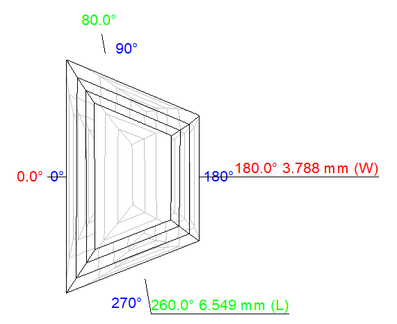
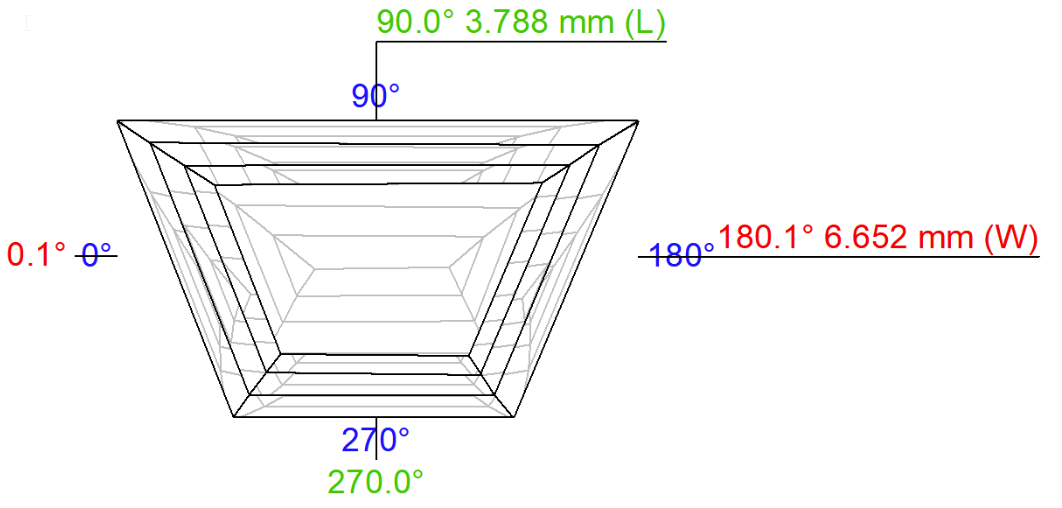
Now model is oriented in report basis in such way that symmetry axis is vertical and most wide width side is located on top.
New definitions of Length and Width for Trapezoid:
Length is measured as local (+-10 degrees from vertical) diameter minimum parallel to vertical axis symmetry direction:
Width is measured as local (+-10 degrees) diameter maximum perpendicular to axis symmetry direction:
There is a documentation Trapezoid Length, Width and some other parameters calculation with detailed detailed information on how to calculate these measurements.
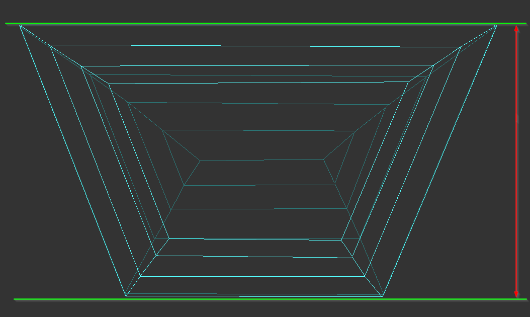
Axis symmetry picture view
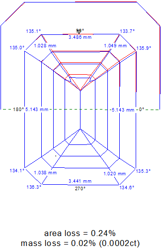
We have moved the placement of the numbers on the axis symmetry pictures for cuts with long girdle facets to improve performance view. This update optimizes the positioning of the numbers, allowing for easier visualization and analysis of the symmetry pictures.
| HPCarbon ver. 1.7.6 | HPCarbon ver. 1.9.2 |
|---|---|
|
|
SmartRecut updates
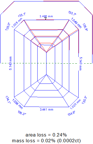
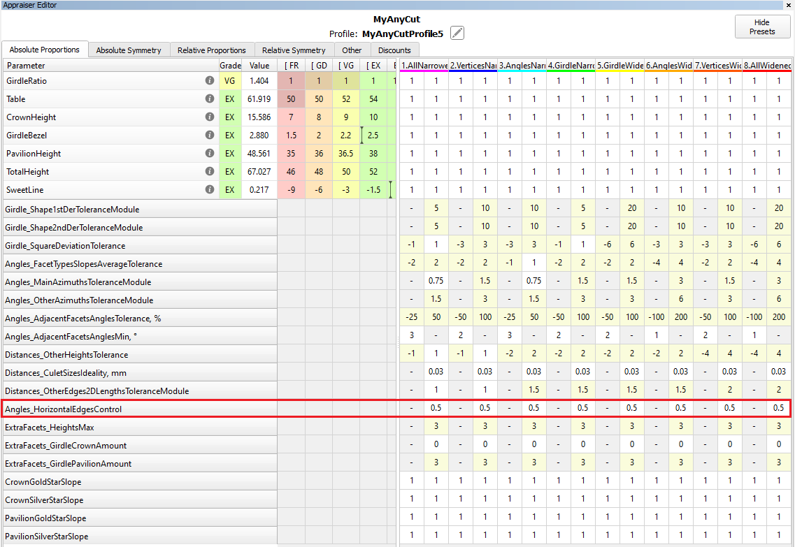
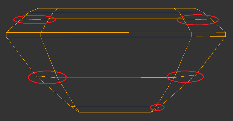
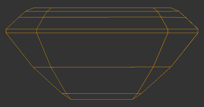
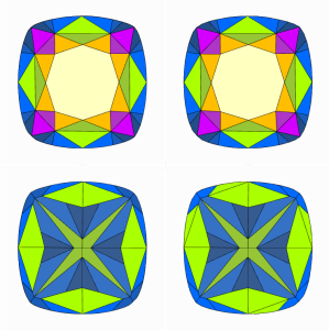
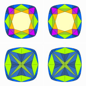
SmartRecut - new parameter - Angles_HorizontalEdgesControl
A new parameter "Angles_HorizontalEdgesControl" is added only to SmartRecut presets. It is necessary to control horizontal edges in step cuts. Parameter value is 0.5° by default. The value of the parameter simultaneously determines what the horizontal edges are and what they should be in SR solutions. The parameter does not apply to the table, culet and girdle edges, they are controlled by other parameters
| Before | Now |
|---|---|
|
|
Facet Types window improvements
Some operations in the Facet Types window were performed automatically without any notification or a user's consent.
The execution of these operations has been corrected.
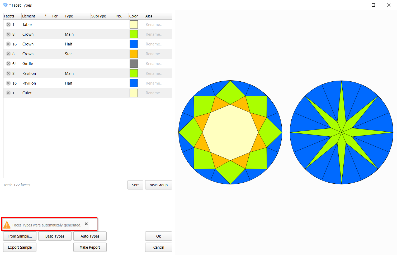
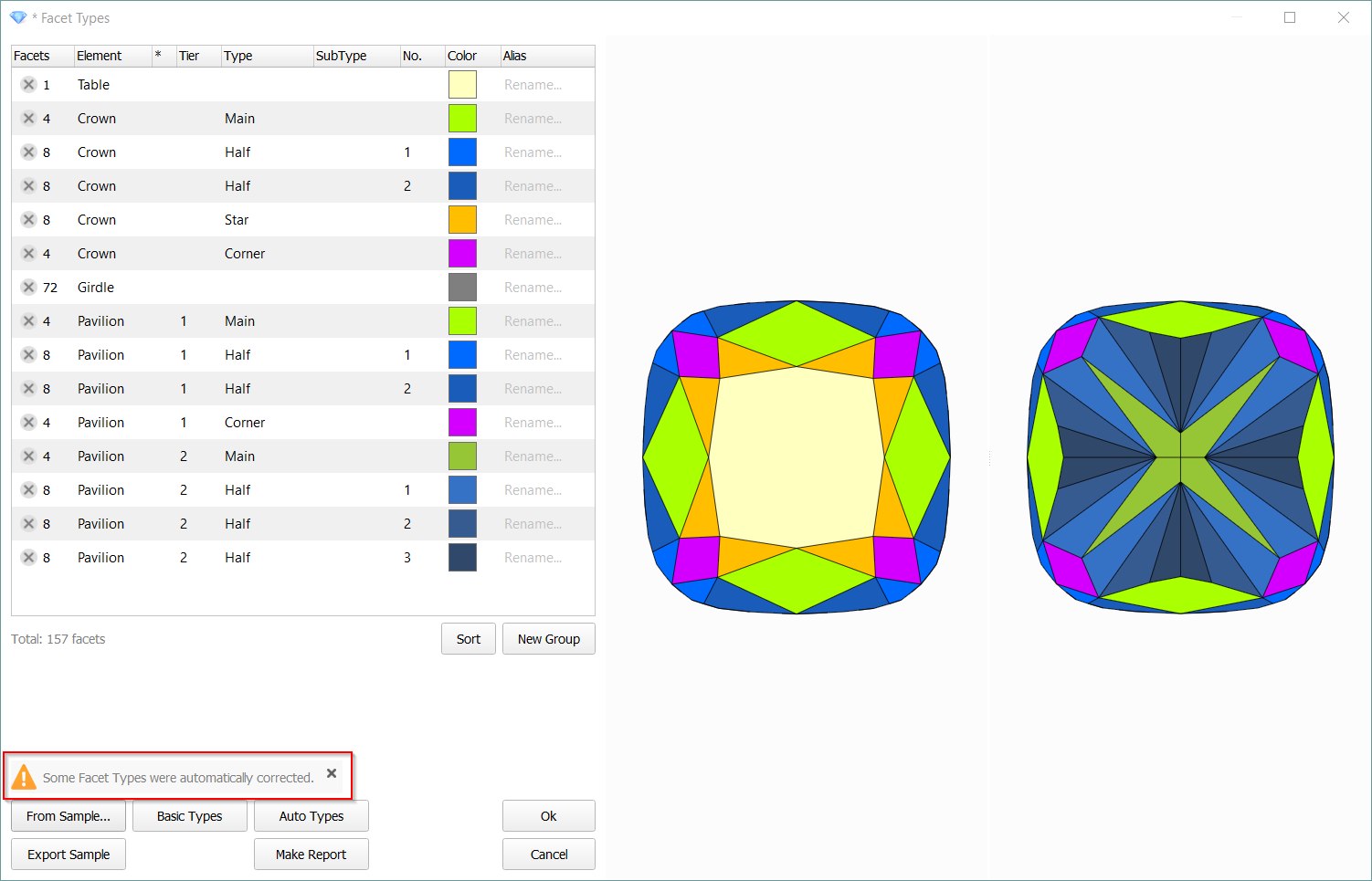
1) The Facet Types are missing or incorrect. In that case the types are automatically generated or corrected, respectively.
Previously, they were applied to the model automatically, even if the user did nothing and closed the window with escape or cancel. There was no clear message that the types were automatically changed. Also, the warning sign on the Facet Types button in the View panel was not working properly.
Now generated (or corrected) Facet Types are not applied to the model automatically, as well the notifications are shown. The user can save the automatic Facet Types by clicking the Ok button or refuse by the Cancel button.
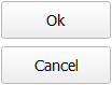
2) The buttons Apply/Close(Cancel) were replaced with standard Ok/Cancel.
| Previously | Now | |
|---|---|---|
|
|
|


3) The "Make Report" button.
Previously, any changes made by an operator were automatically saved, software closed Facet Types window. Herewith, Facet Types could not be undone.
Now changes are not automatically saved and the window is not closed. Thus, a user can cancel the changes after report analysis.
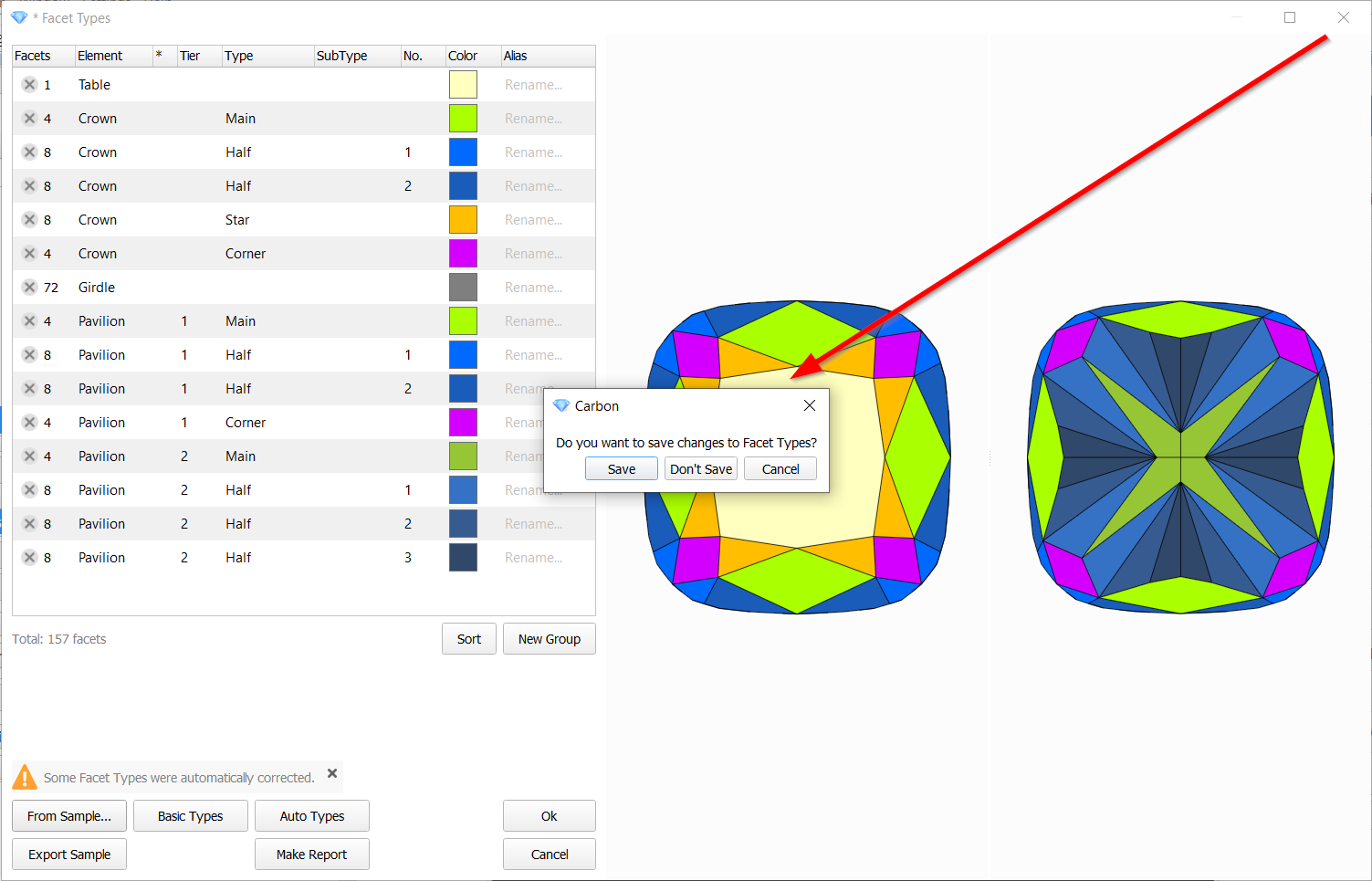
4) The message appears on closing the window if there are unsaved changes.
Building models of groove (concave) cuts within Shadow and XRay models.
Quality Shadow and Reflect models cannot correctly build the concave parts of shapes like Heart, flower and others. XRay model do not have such quality of big flat facets compared to Shadow and Reflect models.
We introduce a new special algorithm which applies grooves (major concavities) from XRay model onto quality shadow/reflect model.
Steps to operate:
- Build the shadow/reflect quality model of the diamond or open existing project with quality model.
- Import the concave model of the diamond (XRay-scan) using recognition option to match the position of the both models.
- Rename the concave XRay scan model as "GrooveShaper" or "grv" to specify this model as source of groove geometry.
- Right Click on the Shadow/Reflect Quality model and choose "Apply Groove".
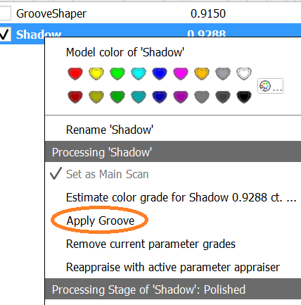
- There will be created a new model with name like "AppliedGroove - Shadow" - this is the result of new algorithm.
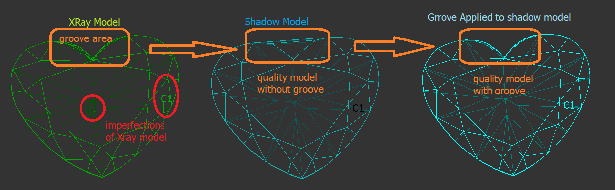
![]() You should not enlarge the groove source model (XRay model) for this process. The new algorithm aimed to preserves the good facets of shadow model ignoring small mismatches and imperfections of XRay model, only deep groove facets are applied to result.
You should not enlarge the groove source model (XRay model) for this process. The new algorithm aimed to preserves the good facets of shadow model ignoring small mismatches and imperfections of XRay model, only deep groove facets are applied to result.
Fixed problems and improvements
- Speeded up model selection for comparison in Comparative I3D Mini View if at least one model from the comparison pair is complex, for instance, an X-Ray model.
- Fixed many bugs in Facet Types transferring for cases when crown and pavilion are strongly distorted but topologically equivalent in two models
| HP Carbon 1.7.6 | HP Carbon 1.9.1 |
|---|---|
| |
| |
|
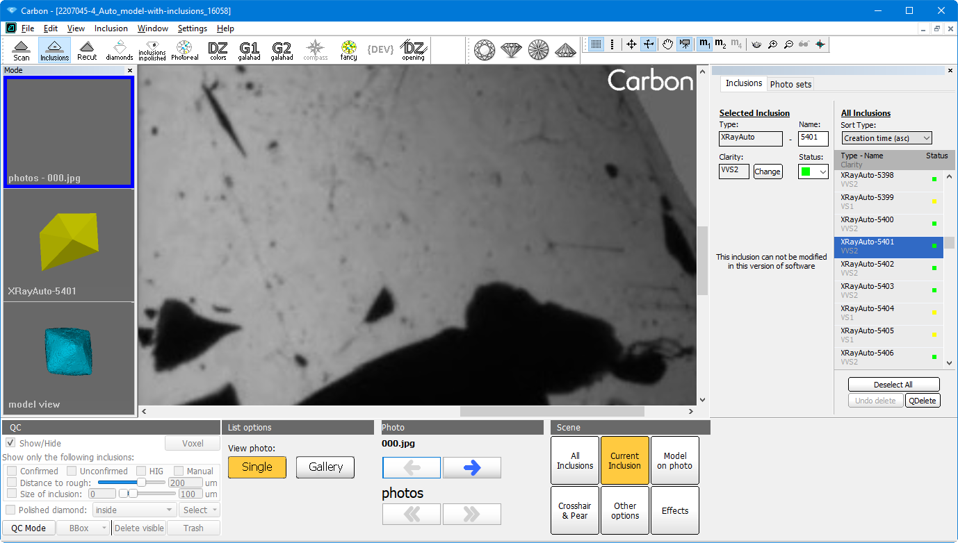
The layout for inclusion plotting and QC is added from M-Box software to HP Carbon software.
Inclusion list is optimized (accelerated) for work with heavy projects containing about several thousand inclusions.
- Speeded up MESM for presets with reference facets
- Corrected culet center calculation in SmartRecut AnyCut with big culets
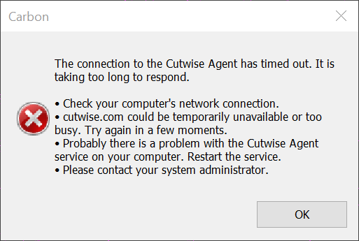
The issue with freezing loading to Cutwise happen on occasion.
Timeouts with a duration of 1 minute and a progress indicator were added to solve that issue.
Add Comment