To compare two stones in HP Carbon, you may use the Comparative Report.
Selecting Models to Compare
Upon selecting the models, one of them is considered the reference one, while the other is considered current. The current model represents the current state of the stone, the reference model represents what we are going to achieve after cutting. If the main scan is included in the comparison, it is used as the current model.
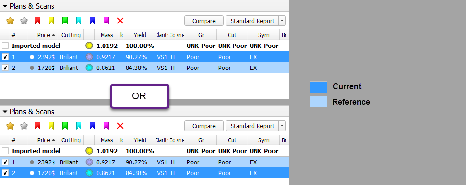
If the main scan is not included in the comparison, the model you select first becomes current (marked with darker blue), second - reference (marked with lighter blue).
Tip
Have only one model selected - it is your current. Then add another - this will become a reference.
Report Types
"Reference - Current" (Main Flow)
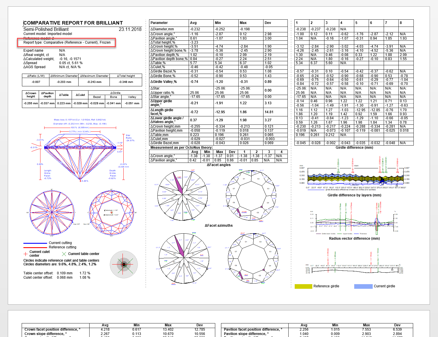
So the main flow for such selection will be clicking the Create Comparative Report button, which produces "Reference - Current" result. The "Reference - Current" means that in the report if the Parameter A = 1,0 for current and = 0,7 for reference, then in the comparative report Parameter A = -0,3 (reference - current = 0,7 - 1,0 = -0,3). Thus, such report shows how this parameter and other parameters should be changed to achieve the desired result (reference) from the current state of the stone.
"Current - Reference" (Alternative Flow)
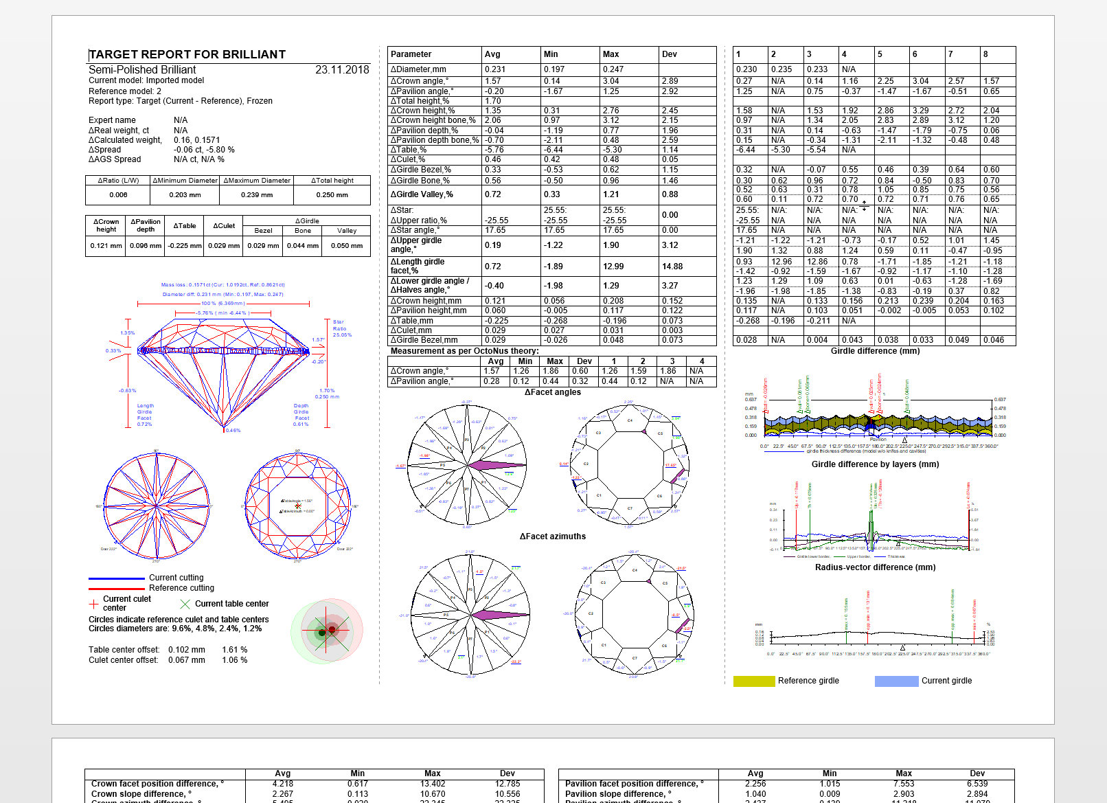
Alternatively, we can use the Create Target Report button, which produces a "Current - Reference" result. Such report shows how parameters of the current state of the stone differ from the desired result (reference).
Generating Comparative Report
To generate a new Comparative Report for the selected models:
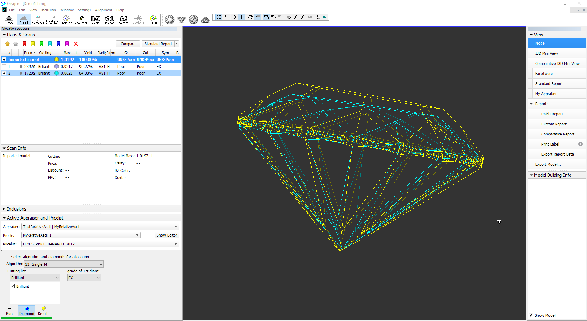
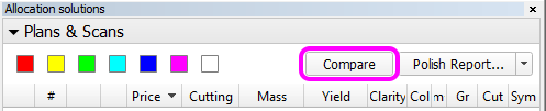
Click Compare in the Allocation Solutions panel.
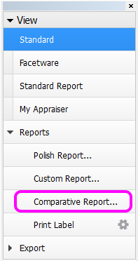
Alternatively, click Comparative reports in the right panel.
Note that the corresponding buttons may be inactive if too many or too few models are selected. See Models management for further clarification.
- A popup window will appear:
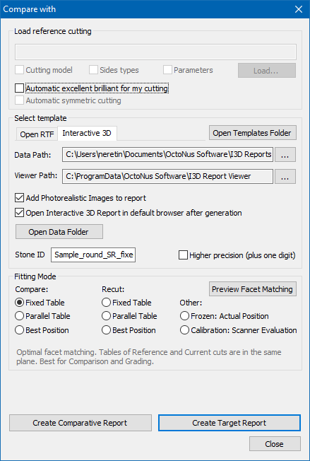
- The Load reference cutting block is intended for use with DiamCalc, and thus not relevant here.
- The Select template block is intended to select the type and format of the report, i.e. RTF or Interactive 3D, and the cut-dependent details.
The Fitting mode determines how the two models are fit together. Upon selecting the models, one of them is considered the reference one, while the other is considered current. If the main scan is included in the comparison, it is used as the current model; otherwise, the solution with lower index is used. Afterwards, the two models are positioned in the following manner for the purpose of the present report:
Mode Positioning Compare: Fixed table Models are positioned for the best facet matching so that the table facets of the models coincide. Compare: Parallel table Models are positioned for the best facet matching so that the table facets of the models are parallel. Compare: Best position Models are positioned so as to achieve the best facet matching without restrictions. Recut: Fixed table Models are positioned for the best facet matching so that the table facets of the models coincide and the reference model fits completely inside the current model (a maximum protrusion of 50um is currently allowed). If it would not fit given the limitations, an error message is returned. Recut: Parallel table Models are positioned for the best facet matching so that the table facets of the models are parallel and the reference model fits completely inside the current model (a maximum protrusion of 50um is currently allowed). If it would not fit given the limitations, an error message is returned. Recut: Best position Models are positioned for the best facet matching with the only restriction that the reference model fits completely inside the current model (a maximum protrusion of 50um is currently allowed). If it would not fit, an error message is returned. Frozen: Actual Position Models are assumed to be arranged exactly as they are in the present file, without any repositioning. Calibration: Scanner Evaluation Models are assumed to be the same (probably in different orientation). This is a special mode intended for hardware adjustment.
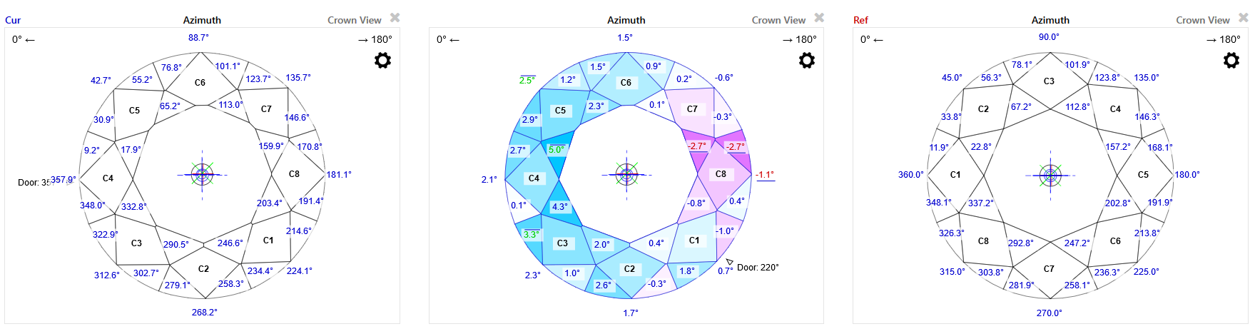
You can preview how the facets of the two models are matched by pressing the Preview Facet Matching button.
A dialog will appear showing both models with facet types indicated by color. You can hover the mouse cursor over any facet to see its properties and highlight a matching facet on the second model.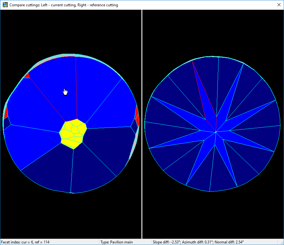
Once you are done with the settings, press Create Comparative Report to compare the current model against reference (i.e. with the reference model oriented as in its own Polish report, and the current model's orientation dependent on it), or Create Target Report to compare the other way around. A report will open up in the browser or MS Word window, depending on the selected report format.
I3D report RTF report 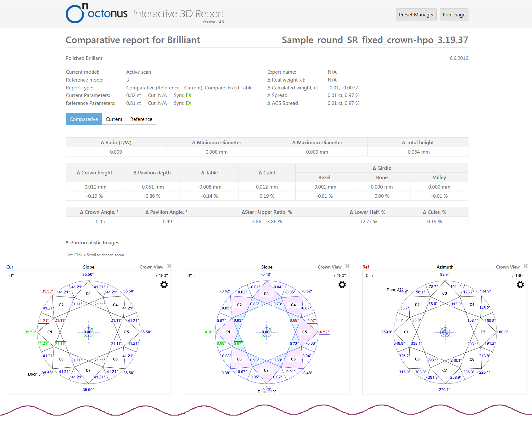
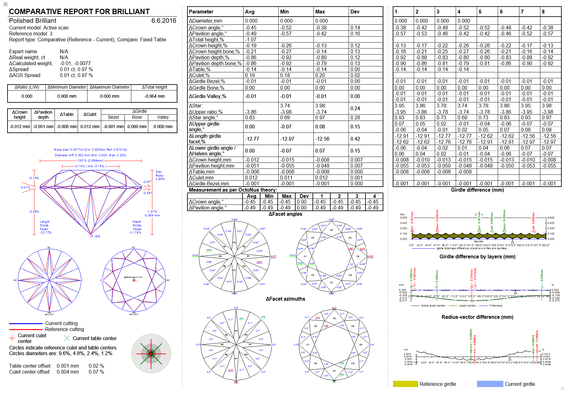
For the ease of comparison, the numbering of facets of the both reference and current models in the comparative report is retained the same as in their corresponding individual polish reports.
Add Comment