| Panel | ||||||
|---|---|---|---|---|---|---|
| ||||||
|
Overview
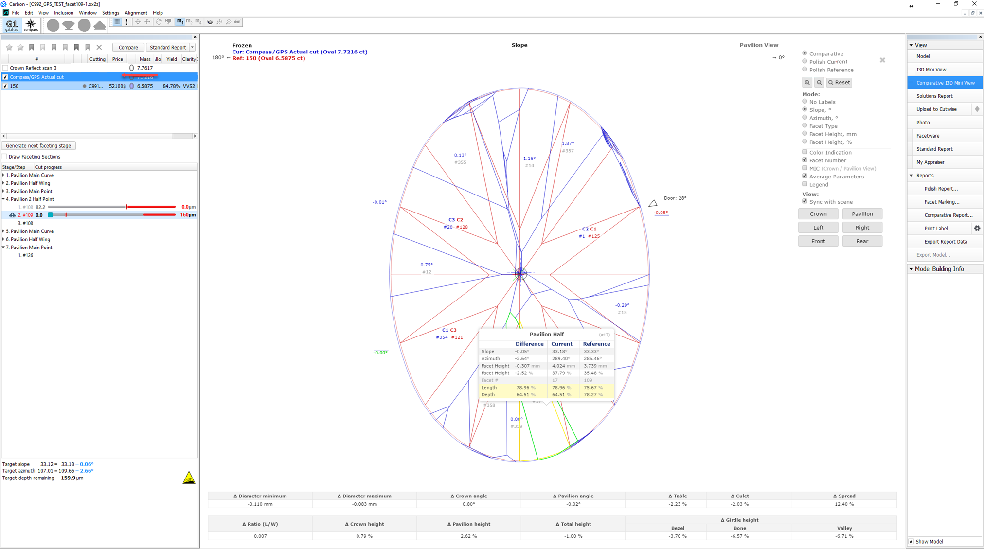
G1 Galahad mode allows visualizing of virtual steps of the cutting process of stone. G1 Galahad mode helps cutter to cut facets correctly by visual control of facet shape and difference values of slope, azimuth, distance between plan and the distance between plan and current model.
G1 mode shows the main scan and active solution (target plan) from Recut mode:
...

...

...
OR
...
In the G1 Galahad mode, you generate polishing steps leading from the current scan to the target solution. Each step is responsible for polishing one single facet, steps are ordered and combined into stages. When working in G1 Galahad, you work with steps and stages and their statuses.
| Note |
|---|
The G1 Galahad mode in HP Carbon is a functionality shared with the Galahad Compass product, thus the information briefly presented in this overview can be explored in detail in the Galahad Compass documentation, specifically, in the release notes. |
For each step, there is a slider bar colored and containing additional numeric data:
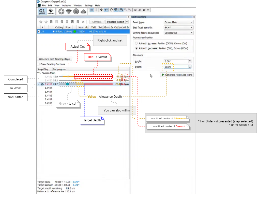
Dragging the pointer on a slider bar leads to the changes in the Scene: it displays how the facet will look "at the selected moment".
About 4 colors:
- In the picture above, three colors are presented
- The border between yellow | red is the polishing target depth (taken into the plan from the target model)
- So red is 50 µm to the right of the target - the area of the overcut
- Yellow is to the left of target is set by Allowance > Depth during a plan creation - this is where the polishing can be stopped and the result will be considered acceptable
- Grey is how many µm you need to polish to reach the left border of Yellow (polishing cannot be stopped here - the result is not achieved yet)
- So where is color #4?
You can right-click at any position of the slider bar and then mark the actual cut in accordance with your stone's current state.
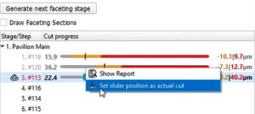
This will lead to:
| If your actual cut is within yellowor red, the step will be marked as "Completed" (grey steps). |
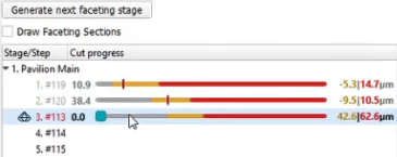
| If your actual cut is within a grey area, you need to continue polishing - the green area will show how many µm you need to cut to reach the left of allowed yellow. |
Order of Work
An important principle is the order of work. and related statuses of steps and stages:
Unfinished Steps
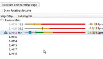
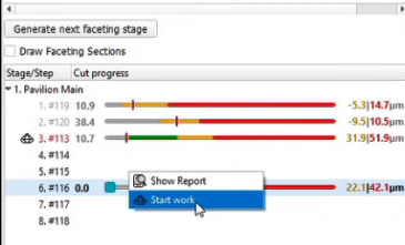
Let us say, you did not finish polishing the step, but want to move to another facet and polish it now. Let us consider an example:
| Here you did not finish work on the facet #113 (now step 3 - "In Work", but decided to Start work on the facet #116. |
| So the system follows your decision: work on the facet #116 is now your step "In Work" and you can start working on it. But pay your attention to what happened with #113 - it was split by the Actual Cut mark into what had already been done (now it is "Completed" step 3) and what is still remains to be done: step 9 at the end of the sequence - the work on #113 should be finished there. |
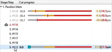
Unfinished Stages
The same approach is now used for stages. To finish stage that has unfinished steps, in the list, right-click the stage and then from the contextual menu, select Finish Stage .
This will split the stage into two - one "Completed" (with all steps that have already been completed), and another "Not Started" - at the end of the sequence, with all steps to be completed.
Actual Cut Model
The " Compass/GPS Actual cut" model is displayed in the solution list. This model is updated each time an actual cut is changed on the faceting step in work. I3D mini and Comparative I3D reports can be built for this model.
Operations with Stages and Steps
You can perform different operations related to stages and steps.
Generating Faceting Stages
To generate the next faceting stage for the selected solution:
G1 mode shows the main scan and active solution (target plan) from Recut mode:
"G1 Galahad" mode "Recut" mode 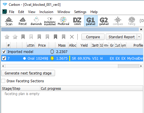
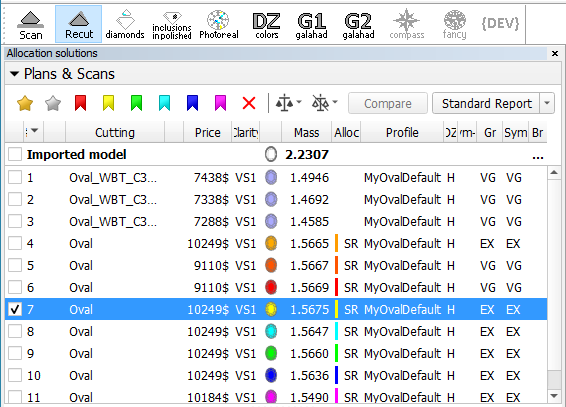
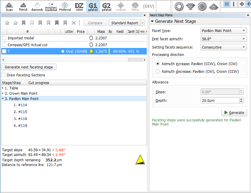
- To get steps, in the Recut mode, select the solution, then go to the G1 mode, and click the Generate next faceting stage button. The Next Step Plans panel is displayed.
- In the Next Step Plans panel, select Facet type, for which you want to generate a stage with steps.
- Set other parameters.
- Click Generate. The stage and its steps are generated and added to the left panel, to the end of the list.
...
Operations with Stages and Steps
You can perform different operations related to stages and steps.
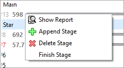
Deleting Stages
To delete the stage:
- In the the G1 Galahad mode mode, on the left panel right-click the stage you want to delete. The context menu is displayed.
- From the context menu, select select Delete Stage. The confirmation dialog is displayed.
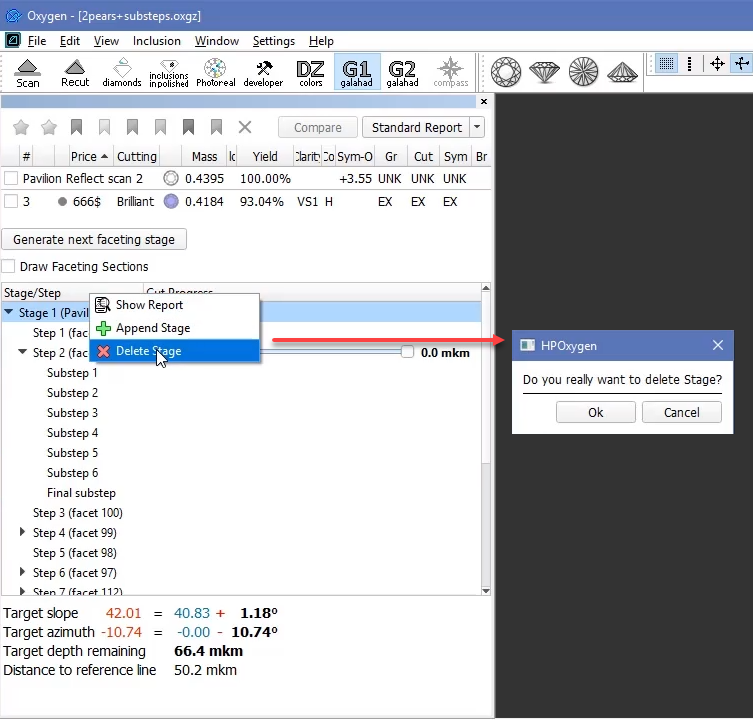
- In the confirmation dialog, click click OK. The stage is deleted along with all steps.
...
- In the G1 Galahad mode, on the left panel do one of the following:
- Right-click the step for which you want to delete the last sub-step.
- Right-click any sub-step within the step for which you want to delete the last sub-step.
- From the context menu, select select Delete last substep. The confirmation dialog is displayed.
In the confirmation dialog, click click OK. The last sub-step of the current step is deleted.

...
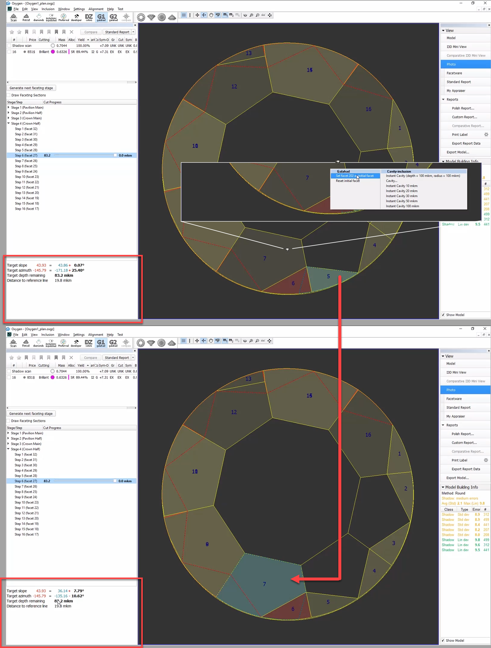
In Galahad Mode, for the selected step it is now possible to manually select the initial facet different from the one automatically calculated by the system. Once manually set, the initial facet can then at any moment be reset to the default one.
Related Pages
...
- Faceting Report
- Galahad Compass release notes: 2020.10.21 - Carbon Compass 1.1.13
- Galahad Compass release notes: 2020.12.10 - Carbon Compass 1.2.12