...
- Scan. Left panel changes to Scan & Build (see below) which can be used to adjust the model (see Model Adjustment ) and to control the hardware if any (see Scanning ). The wireframe model is shown in the Scene.
- Recut. Left panel changes to contain Plans & Scans (see below) (see Models management ) and the features related to recut (see Smart Recut ) and appraising (see GIA Facetware ). The wireframe model is shown in the Scene.
- Diamonds. Left panel changes to Plans & Scans. The model in the Scene changes to the shaded view.
- Inclusions. Left panel changes to Plans & Scans. The Scene is split into two horizontal sub-fields to show inclusions in the polished diamond.
- Photoreal. Left panel changes to Plans & Scans. The Scene is split into two horizontal sub-fields to show the wireframe model and the photorealistic view.
- Developer. The whole window changes to developer mode in order to provide more low-level control of hardware, photosets, etc.
- DZ colors. The whole window changes to DZ mode (see DZ color estimateColor Estimate).
- G1 Galahad. Left panel changes to the mode for managing next step plans for the selected plan (see G1 Galahad).
...
The following additional panels are available:
For more detailed description refer to the corresponding particular examples.
...
| Info | ||
|---|---|---|
| ||
For the Scene in Model or Photos view, you can show the grid. For details, see "Scene Model and Photos View - Show Grid Option" in Adjusting Interface. |
Right
...
Panel
Right The right panel controls the additional panels and reports. It contains the following groups of elements:
|
|


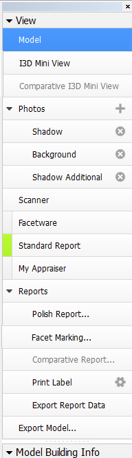
Buttons that control additional panels (Facetware, Standard report, My Appraiser) have an indicator to the left which turns green when the corresponding panel is shown.
...