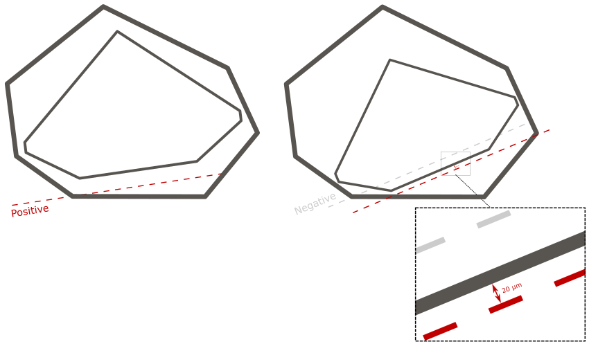
Table processing and reference line parameters are used during the polishing process:
| Table Processing Parameters |
|---|
| Reference Line Parameters |
|---|
| |
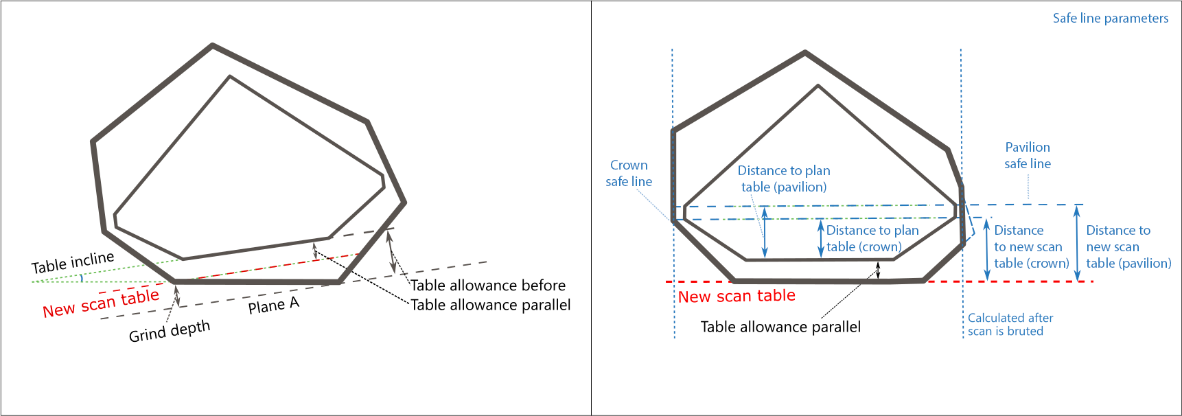
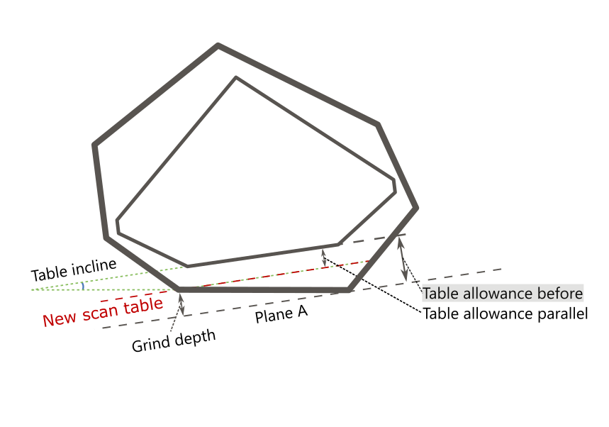
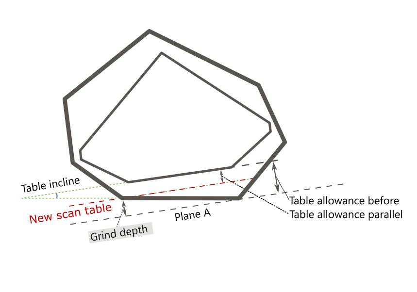
| Plane A | |
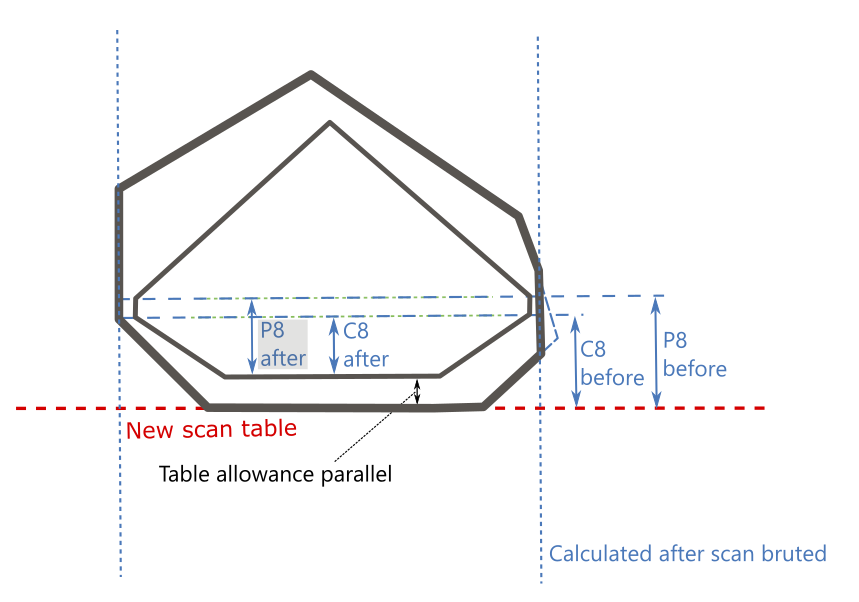
| goes through the point of the scan table farthest from the solution table and is parallel to the solution table. |
| C8 reference plane |
| ("line") - |
| crown main facets reference plane. |
| P8 reference plane |
| ("line") - |
| pavilion main facets reference plane. | |
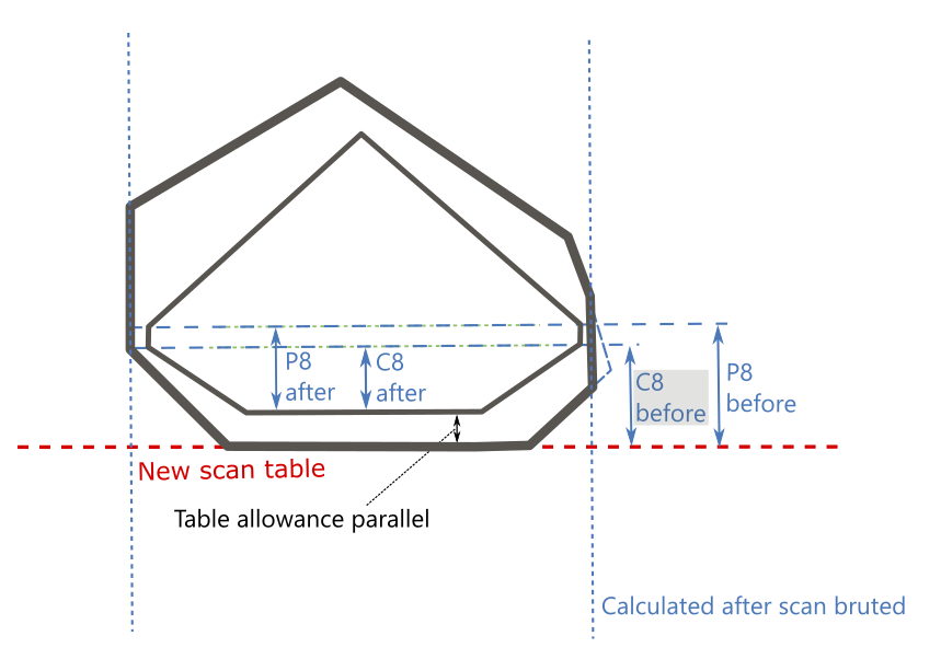
| New scan table | |
| is parallel to the solution table and positioned differently depending on conditions (see |
| Grind depth |
| calculation in the detailed description). |
| Panel | ||
|---|---|---|
|
...
|
Table Processing Parameters
| Parameter | Description | Comment | |
|---|---|---|---|
| Table allowance before | mm | How much should we grind parallel to the solution table to reach it |
- measured |
before |
grinding started. | See the detailed description below. | |
| Grind depth | mm | How much should we grind parallel to the solution table to reach a new scan table |
|---|
| - the one used to set a stone on for bruting. | ||
| Table allowance parallel | mm | Distance between new scan table and solution table. |
|---|---|---|
| Table incline | deg. | Planned table tilt compared to the current holder plane. |
| Expand | ||
|---|---|---|
| ||
How much should we grind parallel to the solution table to reach it - measured before grinding started.
Calculation By finding the distance between Plane A and solution table, where:
Usage and Examples Information is used during grinding. |
...
Reporting
Visualization in Appraisers
|
| Expand | ||||||||||||||||||||||||||
|---|---|---|---|---|---|---|---|---|---|---|---|---|---|---|---|---|---|---|---|---|---|---|---|---|---|---|
| ||||||||||||||||||||||||||
How much should we grind parallel to the solution table to reach a new scan table - the one used to set a stone on for bruting.
Calculation By finding the distance between Plane A and New scan table, where:
Usage and Examples Information is used during grinding. Reporting
Visualization in Appraisers
|
| Expand | ||||||||||||||||||||||||||||||||
|---|---|---|---|---|---|---|---|---|---|---|---|---|---|---|---|---|---|---|---|---|---|---|---|---|---|---|---|---|---|---|---|---|
| ||||||||||||||||||||||||||||||||
Distance between the new scan table (the one used to set a stone on for bruting) and solution table.
Calculation By finding the distance between the New scan table and solution table, where:
Usage and Examples Information is used during grinding. Reporting
Visualization in Appraisers
|

| Expand | ||||||||||||||||||||||||||
|---|---|---|---|---|---|---|---|---|---|---|---|---|---|---|---|---|---|---|---|---|---|---|---|---|---|---|
| ||||||||||||||||||||||||||
Planned table tilt compared to the holder plane.
Calculation NA Usage and Examples Information is used during grinding. Reporting
Visualization in Appraisers
|

Reference Line Parameters
Safe Line Parameters
| Parameter | Description | Comment | ||
|---|---|---|---|---|
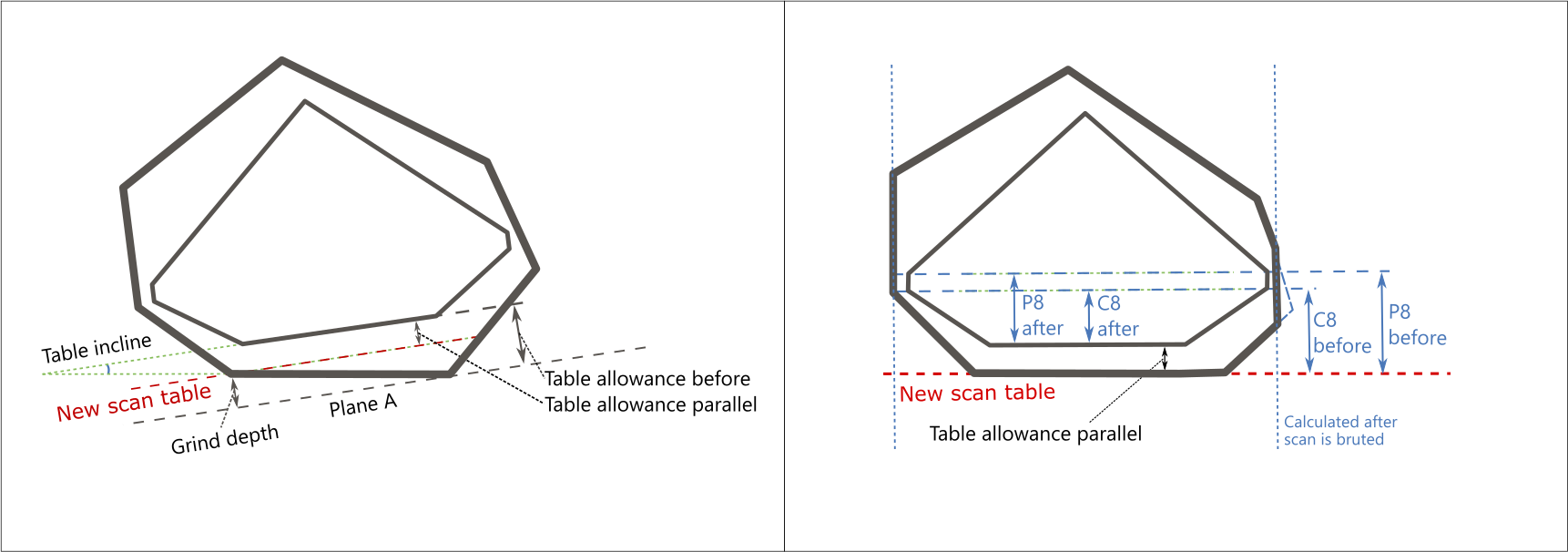
| C8 before | mm | Distance to C8 reference line before grinding from |
New scan table. | Calculated after the scan is bruted. | See the detailed description below. |
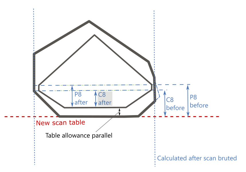
| C8 after | mm | Distance to |
|---|
| C8 reference line after solution table is reached (that is, distance to C8 reference line from solution table itself). | ||
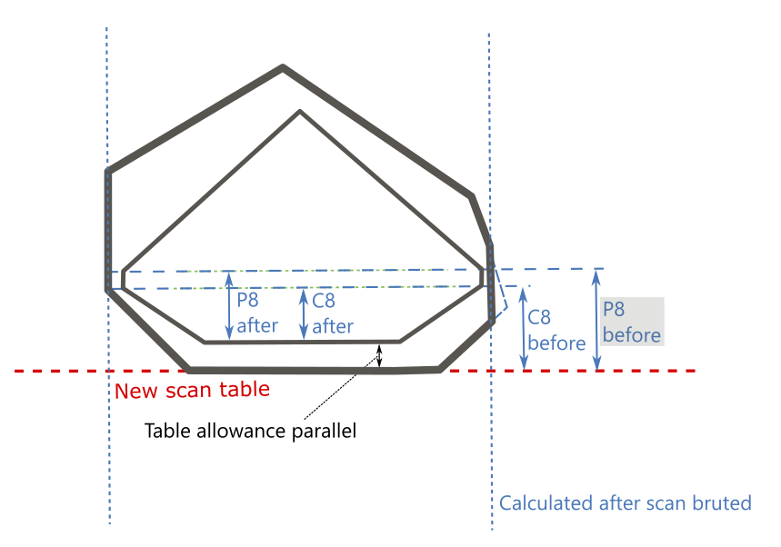
| P8 before | mm | Distance to |
|---|
P8 reference line before grinding from New scan table. | ||
| P8 after | mm | Distance to P8 reference line after solution table is reached (that is, distance to |
|---|
| P8 reference line from solution table itself). |
| Expand | ||
|---|---|---|
| ||
|
...
Distance to Pavilion Safe line before grinding from New scan table.
Distance to C8 reference line before grinding from New scan table.
Calculation Calculated after the scan is bruted by finding the distance between New scan table and C8 reference plane ("line"), where:
Usage and Examples C8 reference line information is used during grinding. Reporting
Visualization in Appraisers
|
| Expand | ||||||||||||||||||||||||||||
|---|---|---|---|---|---|---|---|---|---|---|---|---|---|---|---|---|---|---|---|---|---|---|---|---|---|---|---|---|
| ||||||||||||||||||||||||||||
Distance to C8 reference line after solution table is reached (that is, distance to C8 reference line from solution table itself).
Calculation Calculated after the scan is bruted by finding the distance between C8 reference plane ("line") and solution table, where:
Formal definition: FACETING_REFERENCE_LINE_CROWN_MAINS_AFTER_TABLE = CROWN_HEIGHT_MAX_MM Usage and Examples C8 reference line information is used during grinding. Reporting
Visualization in Appraisers
|
| Expand | ||||||||||||||||||||||||||||||||||
|---|---|---|---|---|---|---|---|---|---|---|---|---|---|---|---|---|---|---|---|---|---|---|---|---|---|---|---|---|---|---|---|---|---|---|
| ||||||||||||||||||||||||||||||||||
Distance to P8 reference line before grinding from New scan table.
Calculation Calculated after the scan is bruted by finding the distance between New scan table and P8 reference plane ("line"), where:
Usage and Examples P8 reference line information is used during grinding. Reporting
Visualization in Appraisers
|
...
| Expand | ||
|---|---|---|
| ||
Distance to P8 reference line after |
solution table is reached (that is, distance to |
...
P8 reference line from |
...
solution table itself).
Calculation Calculated after the scan is bruted by finding the distance between P8 reference plane ("line") and solution table, where:
Formal definition:
Usage and Examples P8 reference line information is used during grinding. Reporting
Visualization in Appraisers
|
These parameters are presented in the Print Label report:
...
