...

4) The rest of the error messages. There is no instruction in them. From the text of the message, you can sometimes understand what the problem is. For example, a specific cut does not interact correctly with the appraiser or reports.

SmartRecut AnyCut Girdle control upgrade
During SmartRecut AnyCut optimization, the Girdle_Shape1stDerToleranceModule and Girdle_PointsAxialSymmetryIdeality parameters can create contradictions. The first one tries to keep the girdle shape of the Recut solution. The second one tries to make the girdle perfectly symmetrical. If the Recut solution girdle is not perfectly symmetrical, then an unresolvable contradiction may result. This is mainly a consequence of user errors during cut registration. Examples of such errors are in Girdle_PointsAxialSymmetryIdeality
In this version, SmartRecut uses Facet Types to determine the symmetrical sectors of the girdle and averages the start girdle shape of the Recut solution over reliable symmetrical sectors. Due to this, the probability of an unresolvable contradiction is significantly reduced. And the correlation between the Girdle_PointsAxialSymmetryIdeality parameter and the AreaLoss value improves.
MyRound Boundaries and GIA Cut grade conflict in SmartRecut
SmartRecut sometimes found solutions with bad GIA Cut Grade due to narrow MyRound boundaries on the parameters Table, CrownAngle, PavilionAngle, StarLength, LowerGirdleLength, GirdleBezel. This program behavior has been fixed. However, SmartRecut still cannot use the space close to the Boundaries between two 6D-cells ("dead zone"). If this happens then there is error message comes to Log:

To fix this problem please refer to the new documentation page Recommendations on Boundaries for main GIA parameters or open below description:
...
| title | Recommendations on Boundaries for main GIA parameters |
|---|
...
GIA Cut Grade Boundaries
Get plans for Brilliant cut that are safe from perspective of GIA cut grade
In HP Carbon, plans for Brilliant cut are allocated with the "GIA Facetware + My Round" appraiser. GIA Facetware rounds the parameters' values.
In some cases, this rounding may cause a problem: when you finish cutting in precise accordance with the plan and the result is scanned, different scanners (for example, yours and GIA lab) may slightly deviate the scanned model. So if our plan was too close to rounding boundaries, the resulting parameter value after rounding may go outside the EX boundaries to VG, etc. This can cause your EX stone from your scanner perspective will unexpectedly become VG from the GIA lab perspective.
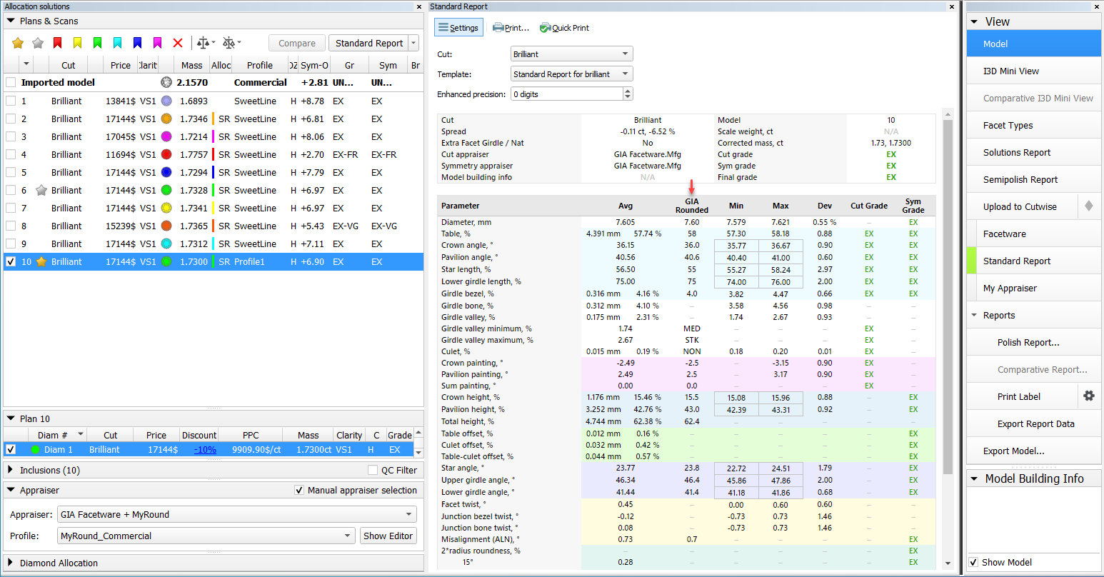
To eliminate this risk, for the Smart Recut algorithm, the new Safe Boundaries mode is added. It is intended to be used when working with Brilliant cut. The mode sets safe distances to a possible GIA rounding. The values are:
| GRID Parameter | Margin | Units |
|---|---|---|
| Table | 0,008 | mm |
| Crown angle | 0,10 | deg |
| Pavilion angle | 0,06 | deg |
| Star length | 1,5 | % |
| Lower girdle length | 1,5 | % |
| Girdle bezel | 0,1 | % |
| Panel | ||||
|---|---|---|---|---|
| ||||
|
| Other GIA Cut parameters | Margin | Units |
|---|---|---|
| Girdle valley Min | 0,1 | % |
| Girdle valley Max | 0,1 | % |
| Culet | 0,1 | % |
| Crown painting | 0,2 | deg |
| Pav painting | 0,2 | deg |
| Sum painting | 0,2 | deg |
| Note |
|---|
At the moment, these values cannot be changed - in the future, it is planned to provide a user interface for viewing/editing. |
The mode is turned on by the Safe Boundaries checkbox.
The mode can be used when running the Smart Recut allocation from Recut solution. However, if you already have a Smart Recut solution previously obtained without using the Safe Boundaries option, it is more effective to run Smart Recut allocation with Safe Boundaries from this previous Smart Recut.
| Note |
|---|
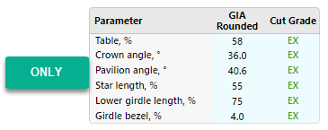
The Table parameter can obtain a value close to the GIA rounding boundary (for example, 58.49%). This means that regardless of rounding up or down (58% or 59%) the required GIA Cut Grade will be produced with the other 5 GRID parameters set. |
SmartRecut + Safe Boundaries upgrade
There are two errors when grading diamonds obtained from SmartRecut solutions by GIA. First — the scanned on different scanners model may slightly deviate. Second — GIA before rounding uses a peculiar way of parameters
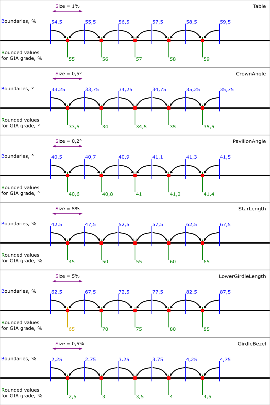
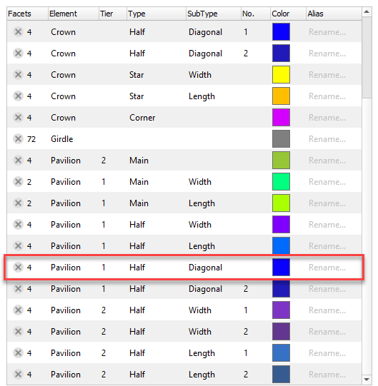
GIA Cut Grade is used during Brilliant Cut optimization with appraiser "GIA Facetware + MyRound". This grade is a complex nonconvex discrete function from 6 parameters: Table, CrownAngle, PavilionAngle, StarLength, LowerGirdleLength, GirdleBezel. The characteristics of this function create problem to use it in optimization algorithms. SmartRecut operates in 2 stages. At the first stage, a solution is sought in a large convex area of the parameters six-dimensional space. Most of the area is of user-defined quality. But there are also parts of the area with less quality. If the optimal by weight solution gets less quality during optimization, then algorithm goes to second stage. At the second stage, the nearest six-dimensional cell of user-defined quality is found and optimization does not go beyond its Boundaries.
The first figure shows for each of the 6 parameters: Boundaries of cells, Size of cells, centers of cells — Rounded values for GIA grade and rounding of average values to Rounded values for GIA grade is illustrated. The values for the figure were taken closer to the center of the EX zone. Exception: There is no EX-combination with LowerGirdleLength = 65.
...
averaging instead of the usual mathematical averaging. But SmartRecut can only use
...
usual mathematical averaging
...
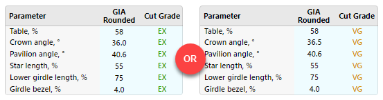
MyRound Boundaries
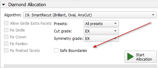
In addition to the GIA Cut Grade, users can set their own MyRound intervals for each of these parameters via Appraiser editor. And these boundaries can create problems for the SmartRecut algorithm.
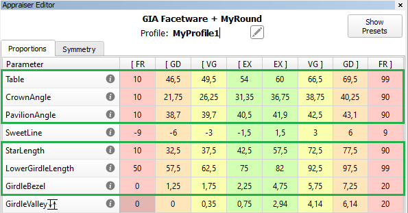
When setting boundaries, it is important to take into account not only Rounded values for GIA grade you want, but also "cells" Boundaries. We recommend setting the Appraiser boundaries for these parameters so that the distance from the left MyRound boundary (Al) to the nearest larger Boundary of the "cell" is more than (0,25 * Size). Similarly, the distance from the right MyRound boundary (Ar) to the nearest smaller Boundary of the "cell" was more than (0,25 * Size). See "Good Appraiser boundaries". Let's call (0,25 * Size) it a "recommended cell size".
For most of the parameters, the "dead zone" is less than "recommended cell size". But after subtraction of the "dead zone" size from "recommended cell size", the optimization has a very small search area, therefore it is statistically more profitable to work in a farther green "cell", and ignore the red "cells". See "Bad Appraiser boundaries".
Even more bad situation for optimization when there are no green cells. See "Problem Appraise boundaries". And there are enough one-parameter bad boundaries to make all 6D-cells are red. For example, LowerGirdleLength [77, 78.4] or narrower boundaries create this situation. At the time of Carbon 1.4.4, the second stage of SmartRecut does not correct the quality of the GIA Cut Grade in such situations. In the future, one of the red "cells" will be selected in such a situation, but this does not cancel the recommendation about "recommended cell size" = (0,25 * Size).
. In the previous version both errors was including in Safe Boundaries margin. Therefore, if we added the full margin to the solution Math values then it was ok. But if we added the full margin to the solution GIA values, then it was possible to go beyond the GIA Cut grade.
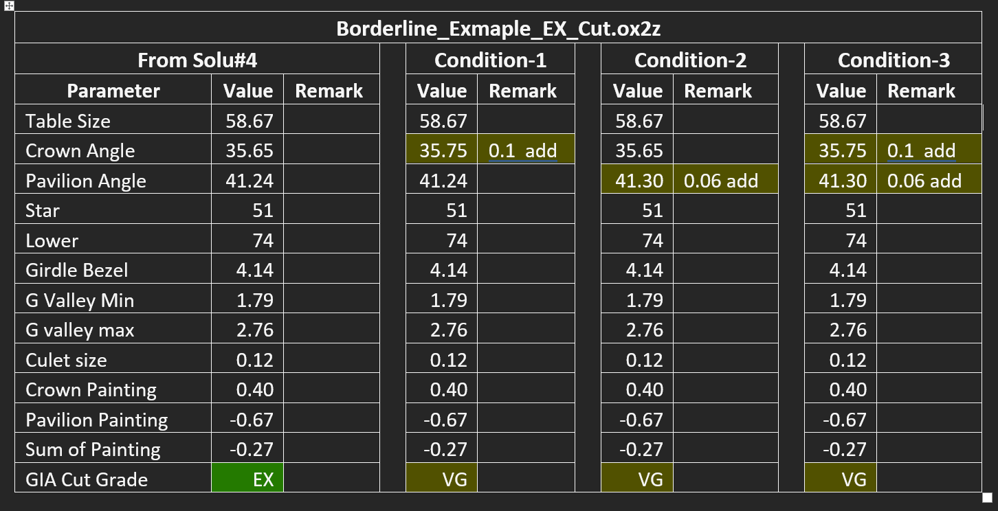
In the current version Safe Boundaries margin is responsible only for the possible scanner error. And SmartRecut separately takes into account GIA rounding error (dead zone). So you can add the full margin to the solution GIA values, it will be ok.
MyRound Boundaries and GIA Cut grade conflict in SmartRecut
SmartRecut sometimes found solutions with bad GIA Cut Grade due to narrow MyRound boundaries on the parameters Table, CrownAngle, PavilionAngle, StarLength, LowerGirdleLength, GirdleBezel. This program behavior has been fixed. However, SmartRecut still cannot use the space close to the Boundaries between two 6D-cells ("dead zone"). If this happens then there is error message comes to Log:
To fix this problem please refer to the new documentation page Recommendations on Boundaries for main GIA parameters or open below description:
| Expand | ||||||||
|---|---|---|---|---|---|---|---|---|
| ||||||||
|
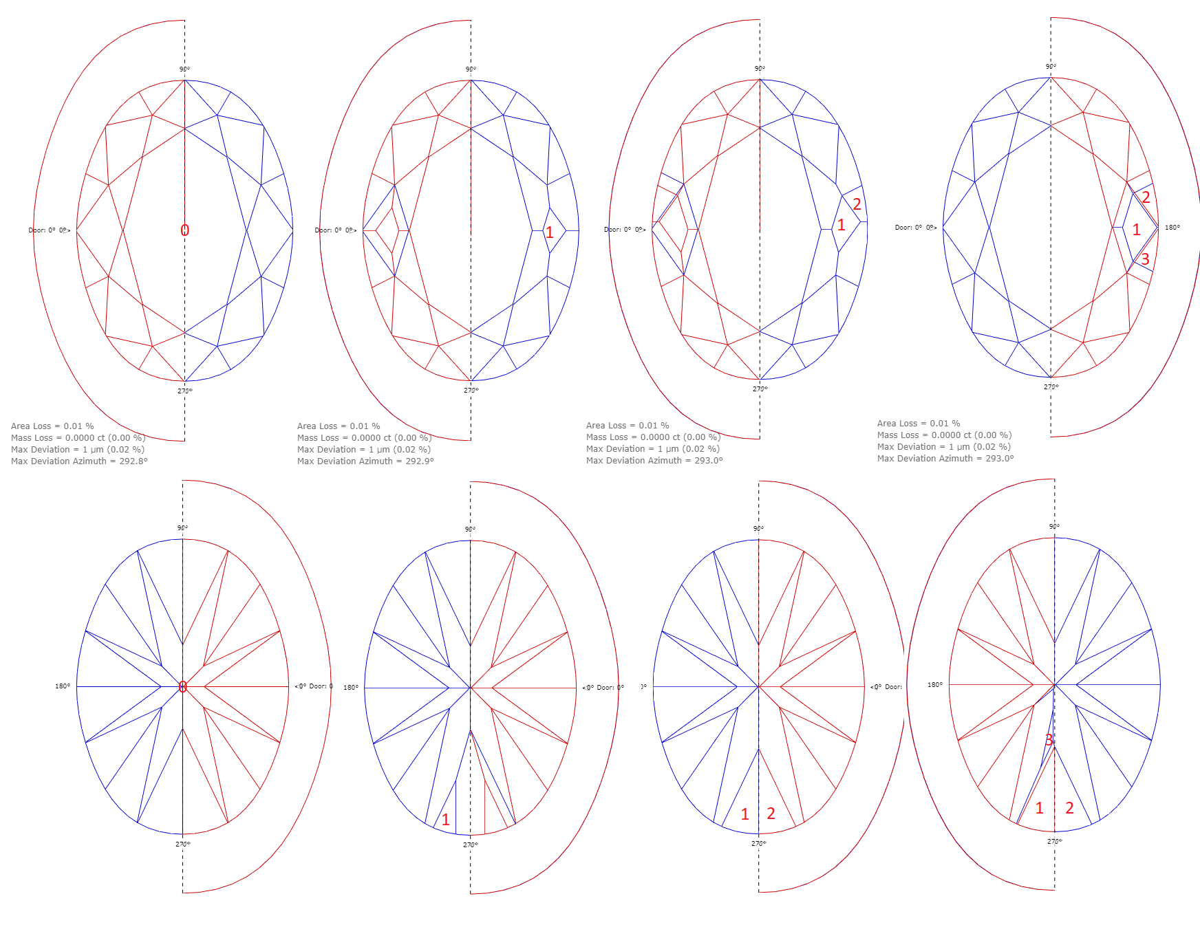
SmartRecut AnyCut Girdle control upgrade
During SmartRecut AnyCut optimization, the Girdle_Shape1stDerToleranceModule and Girdle_PointsAxialSymmetryIdeality parameters can create contradictions. The first one tries to keep the girdle shape of the Recut solution. The second one tries to make the girdle perfectly symmetrical. If the Recut solution girdle is not perfectly symmetrical, then an unresolvable contradiction may result. This is mainly a consequence of user errors during cut registration. Examples of such errors are in Girdle_PointsAxialSymmetryIdeality
In this version, SmartRecut uses Facet Types to determine the symmetrical sectors of the girdle and averages the start girdle shape of the Recut solution over reliable symmetrical sectors. Due to this, the probability of an unresolvable contradiction is significantly reduced. And the correlation between the Girdle_PointsAxialSymmetryIdeality parameter and the AreaLoss value improves.
SmartNormalize automatically fixes simple errors in FacetTypes
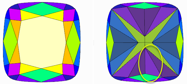
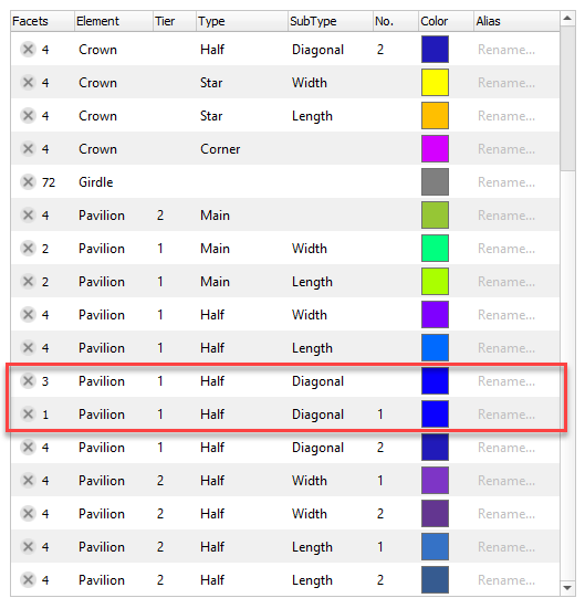
To increase model symmetry and remove excess facets, you can use the Smart Normalize algorithm. Previously, if the model that you were going to normalize had mistakes in its facet types, Smart Normalize could provide non-symmetrical solutions. Now the algorithm is improved: it tries to fix mistakes in facet types and then provides excellent symmetry.
Hint This is especially useful when mistakes are not obvious to an operator.
Technical details:
- The algorithm tries to fix facet type mistakes using information about groups of symmetrical facets and which type dominates in a group. If the situation is clear enough, mistakes in facet types are fixed automatically and the algorithm finds the solution with the correct number of symmetry axes. If the case is too complex, the algorithm uses initial facet types without changes.
- Fixing does not change the initial model facet types but does change the resulting model - it will have different (fixed) facet types.
Example:
| Easy to see with the eyes | Not obvious to an operator | |
|---|---|---|
| Initial model |
|
|
| Normalized model |
|
|
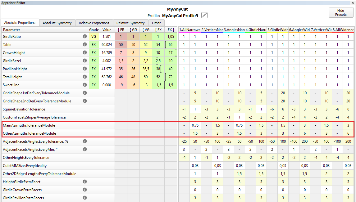
Control absolute value azimuths for in-house cuts
In previous versions, for in-house cuts the algorithm 19. SmartRecut (Brilliant, Oval, AnyCut) controlled only the azimuths symmetry of the facets. But a change in the absolute value of azimuths could lead to a big loss of the solutions performance.
Therefore two parameters have been added to control the tolerance of azimuths from the initial values. More "narrow" MainAzimuthsToleranceModule is tuned for only Main facets. Less "narrow" OtherAzimuthsToleranceModule is tuned for other facets.
Precise fixation of parameters StarLength and LowerGirdleLength in SmartRecut (Brilliant)
StarLength and LowerGirdleLength are parameters that greatly affect the pattern of the stone, but practically do not affect the mass. Sometimes there is a need to get a specific average value for these parameters. Now you can do this by setting an interval of 0.02 length in MyRound. SmartRecut solutions will have the value exactly in the center of the interval. However, when setting narrow boundaries, it is necessary to take into account the dead zone, especially when working in Safe Boundaries mode. You can find out more information on the new documentation page Recommendations on Boundaries for main GIA parameters

Reports improvements
New report type - Rough Report
Objective
A manager receives a batch of stones, these each are in their own package. A Rough Report is printed in a small size and applied to a package with a stone.
The Rough Report is needed so that the manager can quickly check what was expected to do with the stone not opening its package.
Controlled diamonds' parameters: weight, cut quality, appraisers, Crown and Pavilion angles, etc.
Creation of Rough Report
- An operator sets the starting position of the stone in the HP Carbon scene for further an image generation.
The main scan or a solution could be rotated. Stone position in Rough Report is synchronized with the HP Carbon Scene.
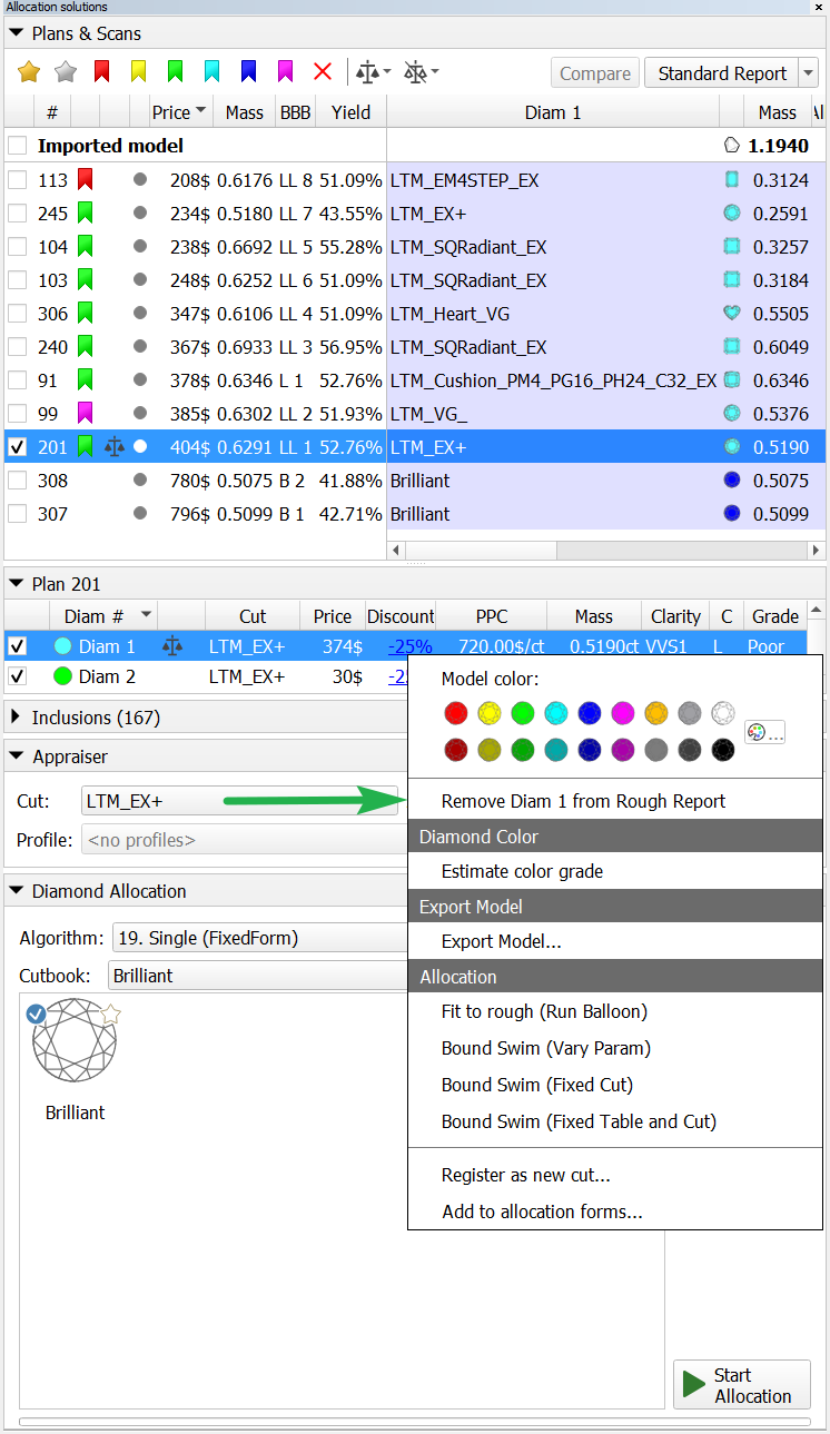
- The operator selects the solution to be made in the Plans & Scans panel.
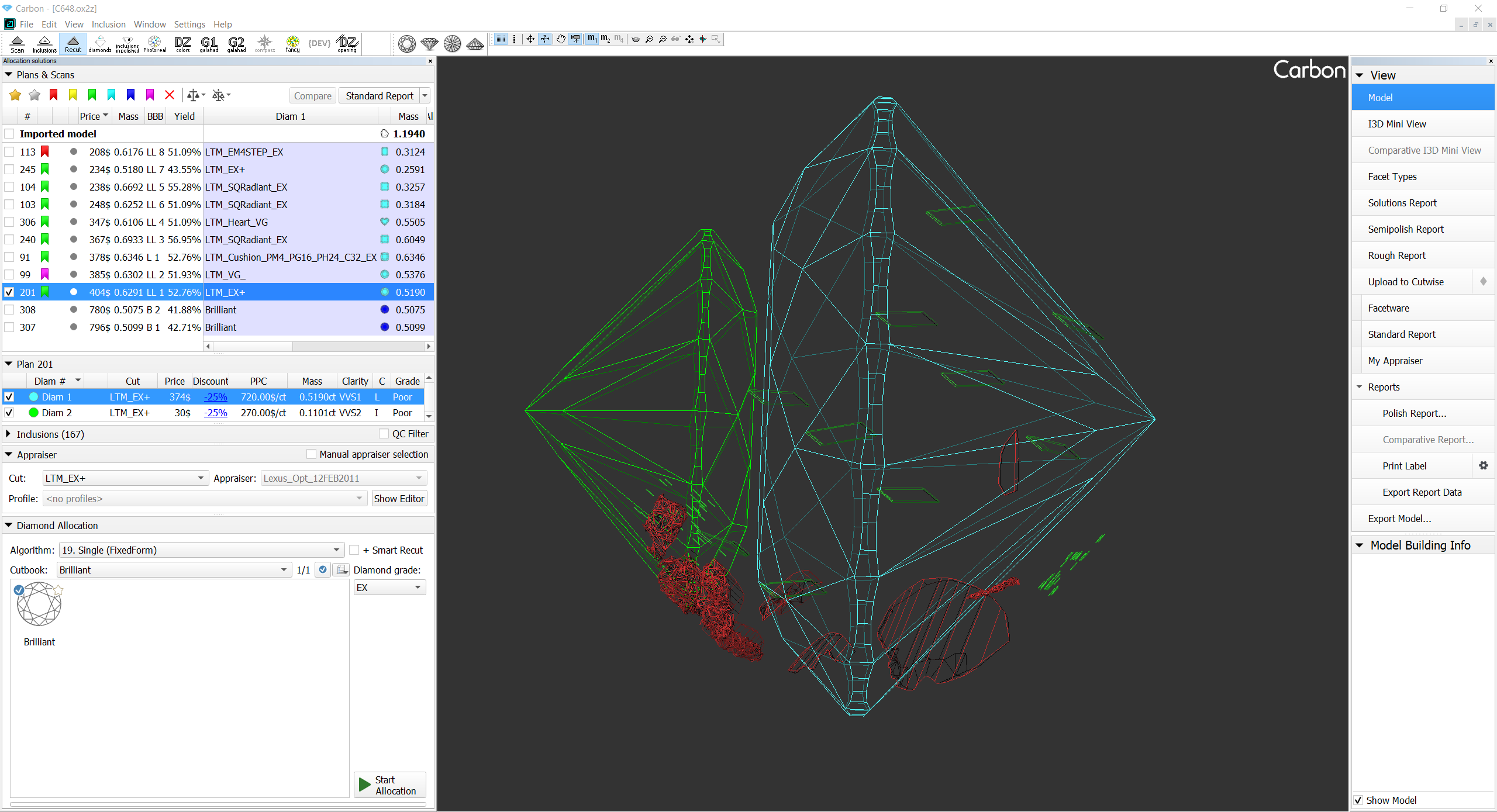
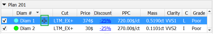
- The operator can select diamonds to be included into the report.
All diamonds are shown in Rough Report by default. Diamonds could be added or removed in opened report it will be updated in this case.
This is done using the context menu in the panel containing diamonds info for the current solution.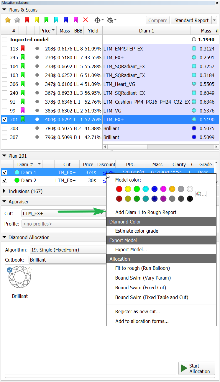
- Open Rough Report panel.
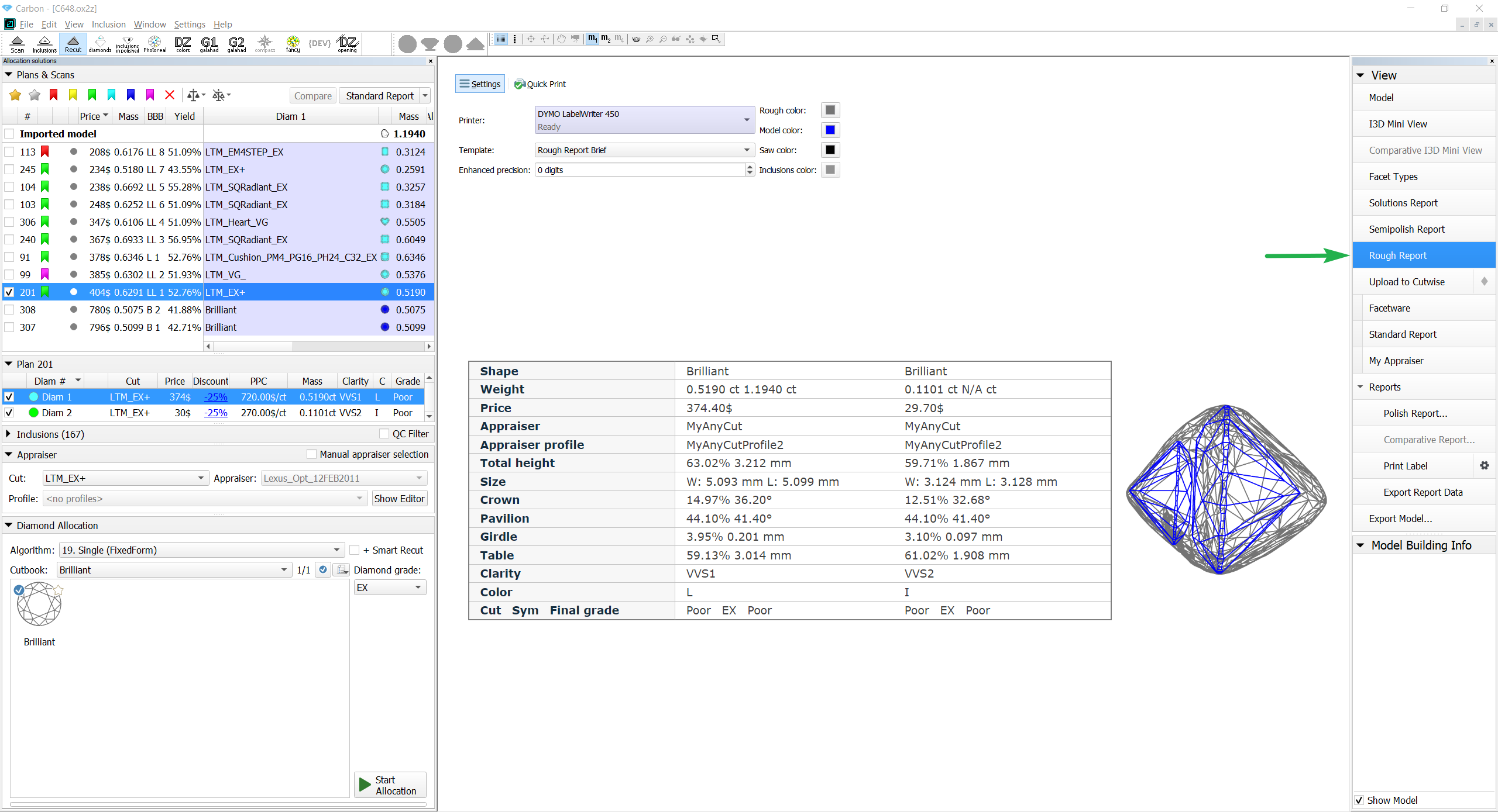
- Selection of a printer. The selected printer is saved in HP Carbon and will be shown at further openings of Rough Report.
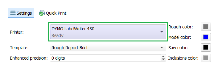
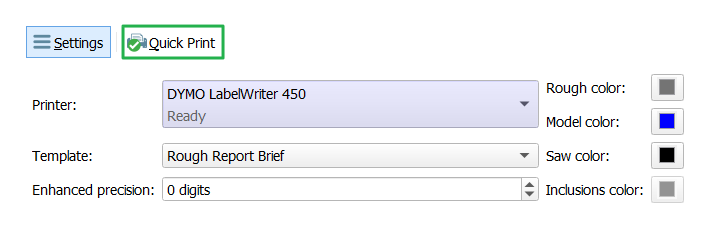
- Print the Rough Report.
Rough Report features
The operator can change colors in Rough Report (Rough, Model, Saw, Inclusions). It will be updated at a color changing.
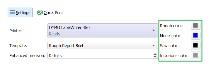
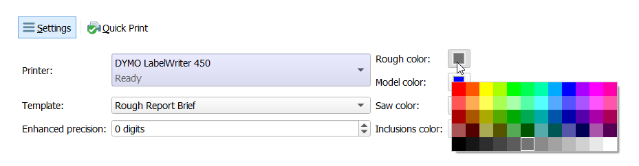
Also enhanced precision could be changed in the range [-3, 3] digits. The report will be updated at an enhanced precision changing.
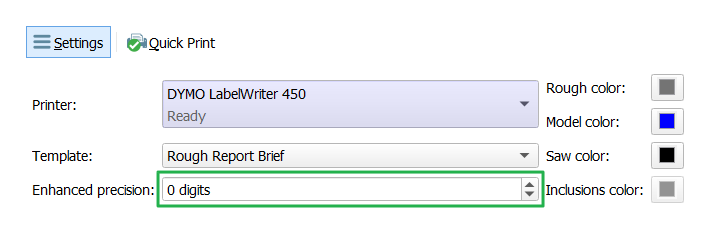
All settings are saved in HP Carbon.
The Rough Report will be updated at selection of another solution.
![]() Inclusions while aren't embedded in Rough Report images.
Inclusions while aren't embedded in Rough Report images.
Illustrated HTML Report templates for many other cuts are available (besides RBC)
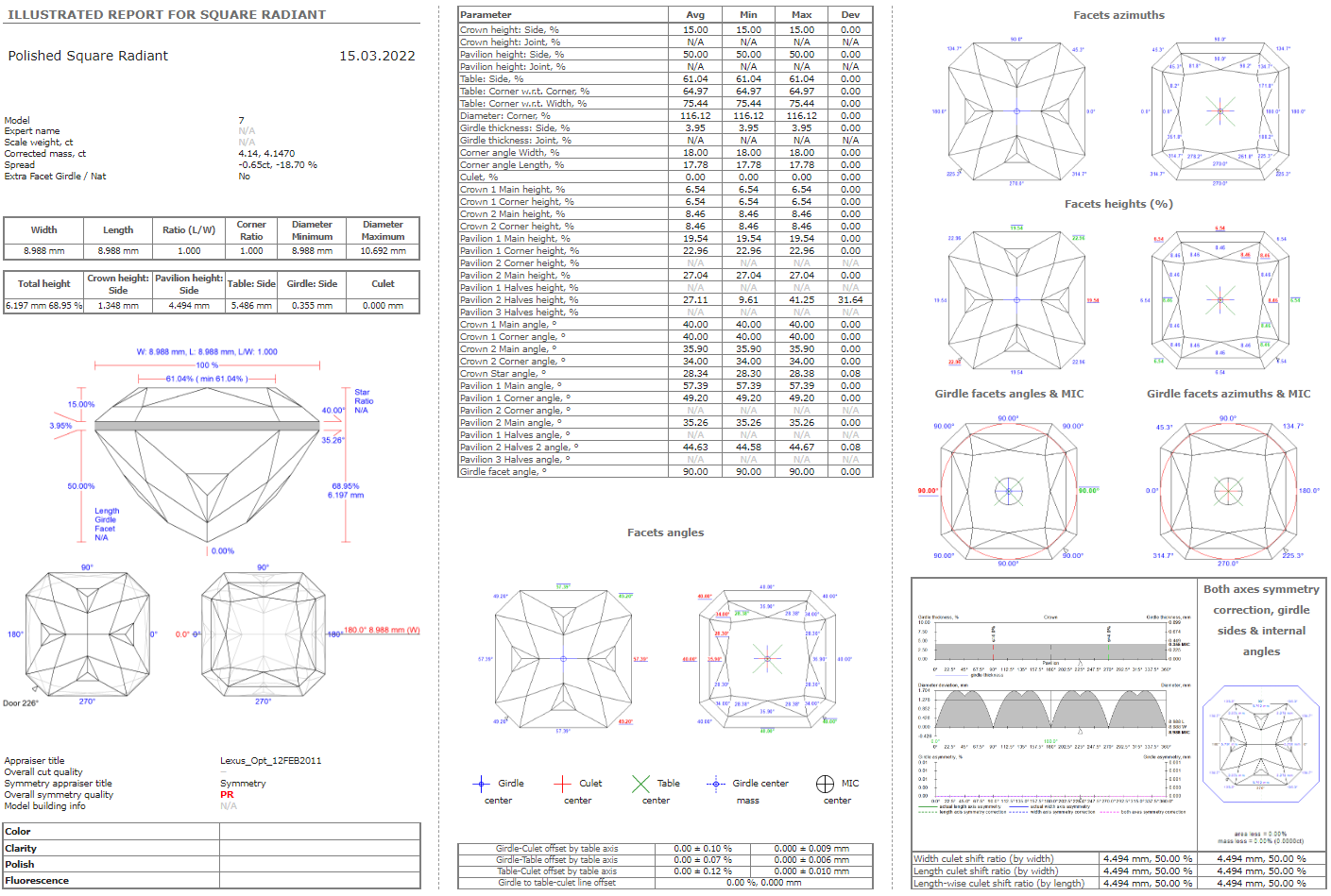
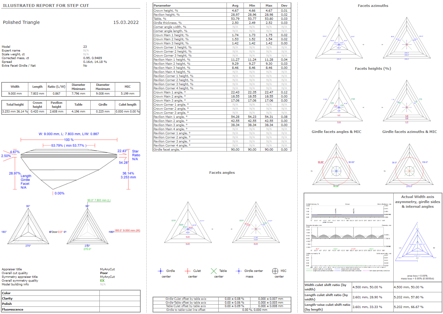
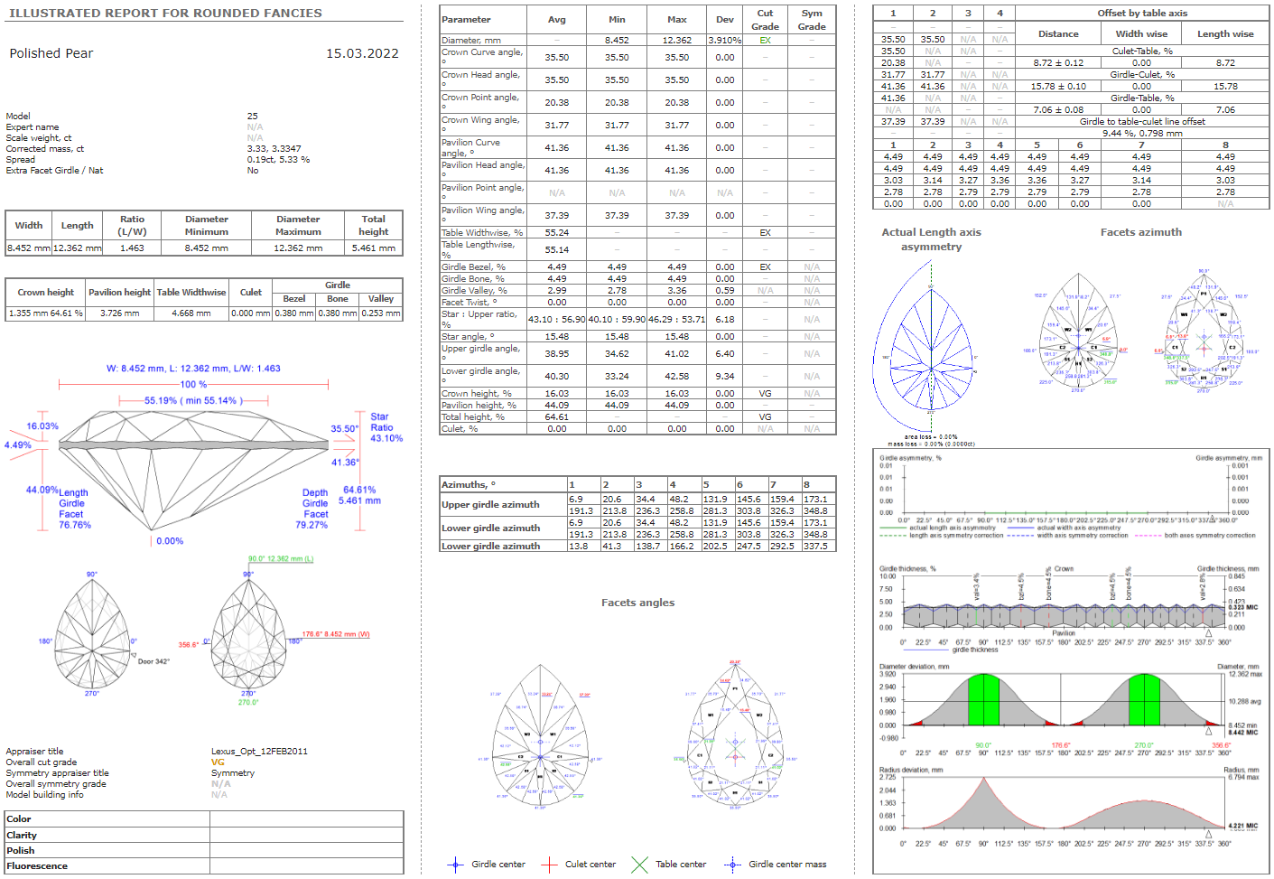
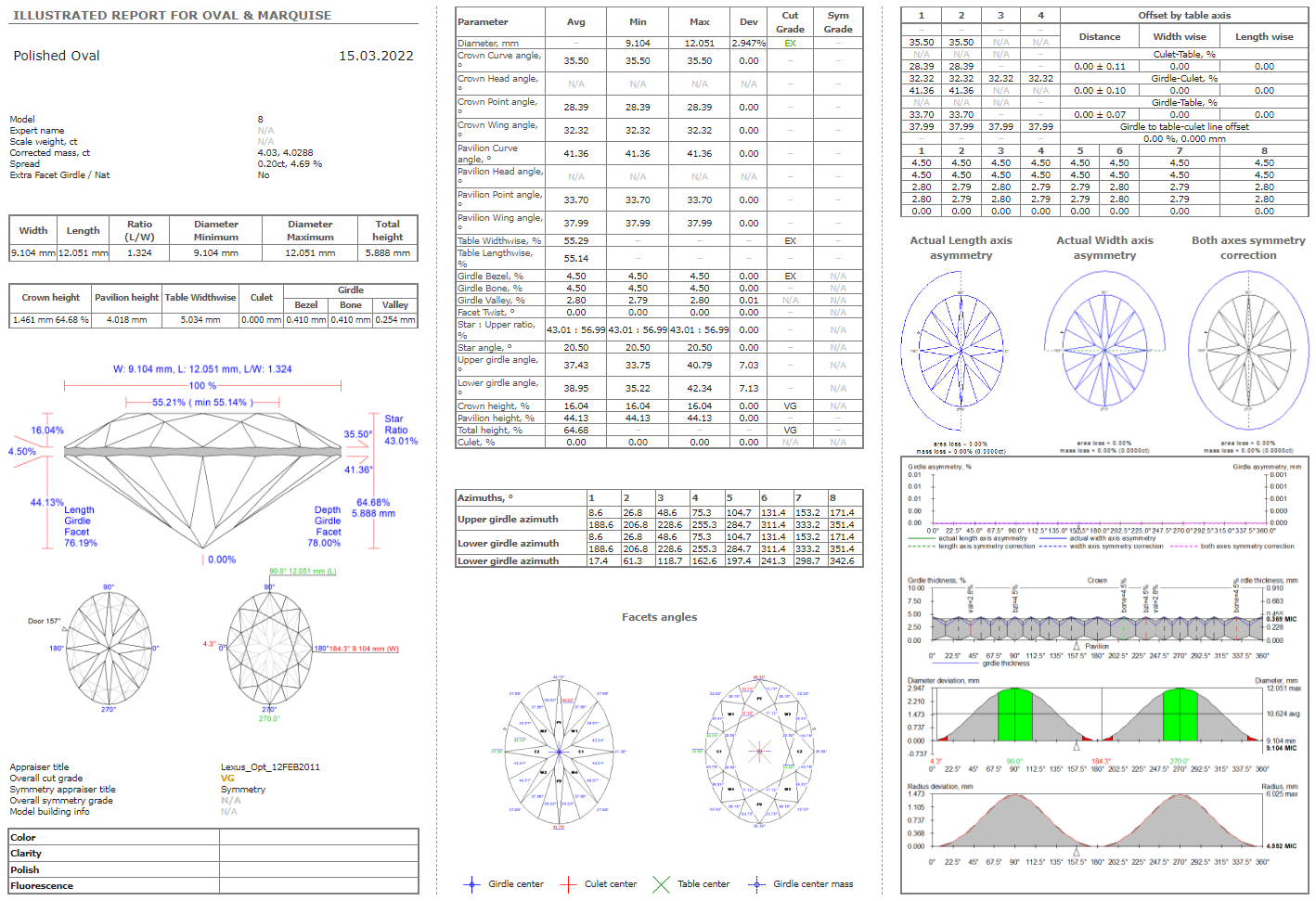
The convenient single-page reports in HTML format have been made for most types of cuts (as was previously done for RBC), so that the operator, without the need to use MS Word, could open the main parameters of the model on the screen on one page and transfer them to the clients/auditor/manager:
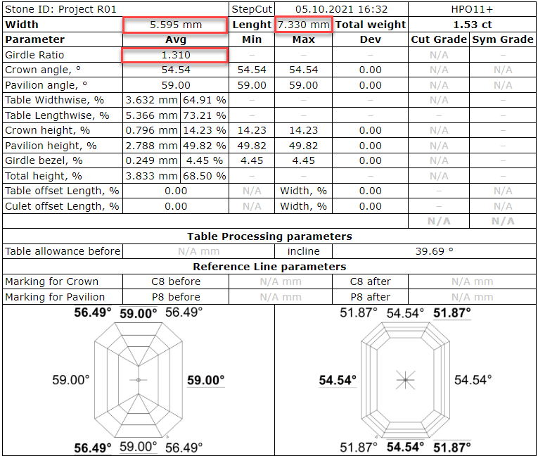
- Polished HTML Illustrated Report Step Cut;
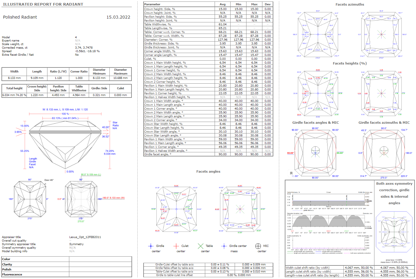
- Polished HTML Illustrated Report Radiant;
- Polished HTML Illustrated Report Square Radiant;
- Polished HTML Illustrated Report Triangle;
- Polished HTML Illustrated Report Rounded Fancies;
- Polished HTML Illustrated Report Oval-Marquise.
These reports are located in "Polish Report..." for a specific type of cuts, for an example:

Examples of reports:
1) Illustrated HTML Report Step Cut 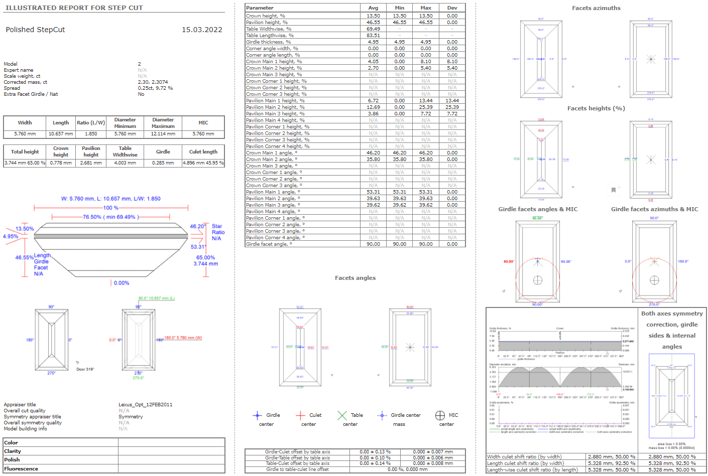
2) Illustrated HTML Report Radiant
3) Illustrated HTML Report Square Radiant
4) Illustrated HTML Report Triangle
5) Illustrated HTML Report Rounded Fancies
6) Illustrated HTML Report Oval&Marquise
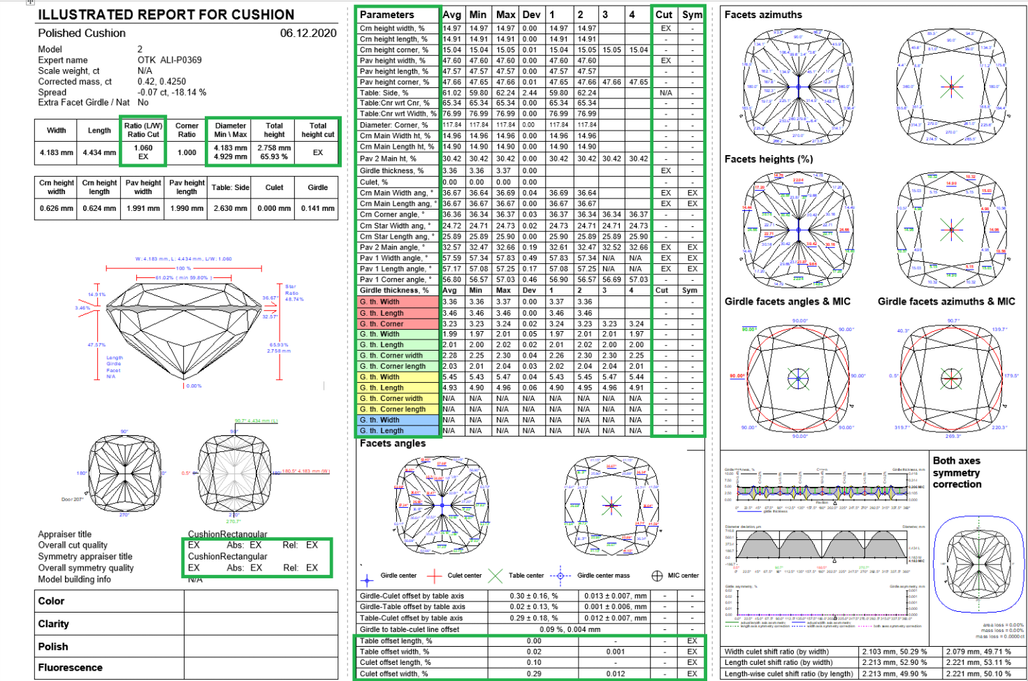
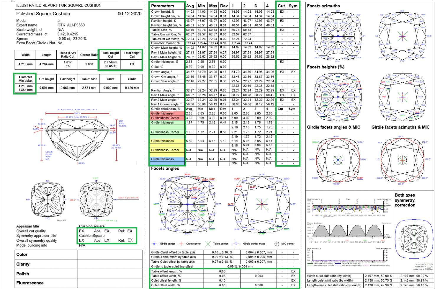
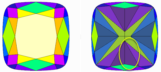
View grades for Cushion cuts in reports
For the Rectangular and Square Cushion cuts the grades were added to the following reports:
- Standard report
- HTML Illustrative report
- RTF Illustrative report
- Label report
Some minor layout changes were caused by this change (shorten parameter names and display positions.
| Rectangular Cushion | Square Cushion |
|---|---|
|
|
View with and length for lengthened cuts
Information about the width, length, and girdle ratio is added to:
- Label and Semipolish reports for all cuts.
- Standard reports for all cuts except Brilliant.
Algorithms of allocation
New algorithm "21. Next" for allocation
To add one more diamond to already created solution you can use algorithm "21. Next". The next diamond will be added in maximal possible free zone of rough volume which is not occupied by created before diamonds. A position of existing diamonds is not changed.
Important! Algorithm "21. Next" during work takes into account allocation forms of Cut that allows to find better solutions for in-house cuts. Note that algorithm Find Next Diamond in Helium Rough / Pacor Client doesn't work with many allocation forms so we recommend to use "21. Next" and HP Carbon to find next diamond.
Before run of algorithm please make sure that you select one or several solutions where you want to add one more diamond and cut types from Cutbook.
There is possible to create solutions composed of 2, 3, 4 and so so diamonds.
There is a sample of algorithm "21. Next" work:
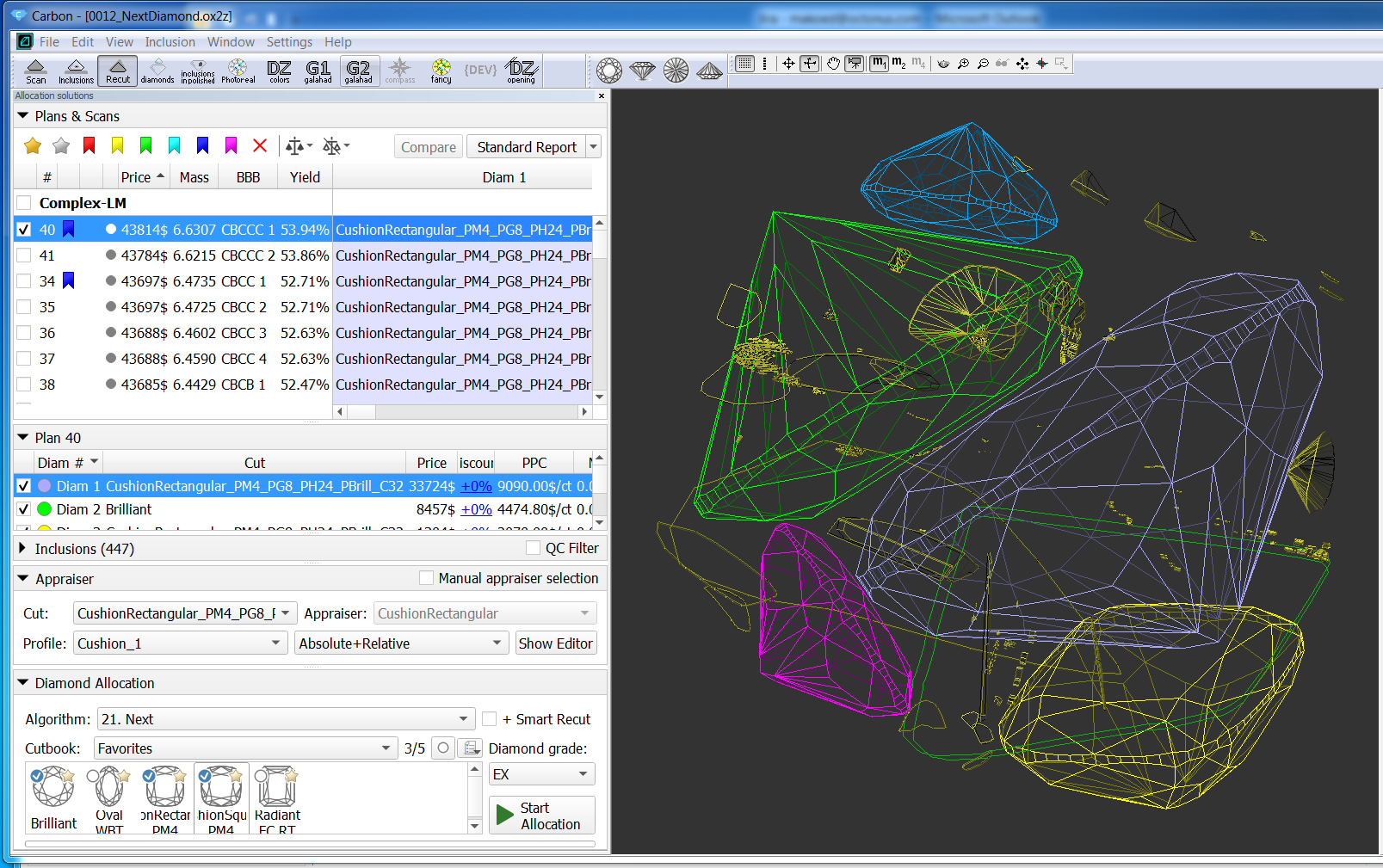
0012_NextDiamond.ox2z
Sol. #40 contains 5 diamonds, it was allocated sequentially from sol. #24, 30, 34.
New algorithm "22. MESM for blocking"
We have implemented a new algorithm: Minimum Enclosing (Encompassing) Symmetrical Model - "22. MESM for blocking"
The algorithm finds the Minimum Enclosing Symmetrical Model. Then inflates this model by 100 microns. Then it offsets 3 adjacent faces on the pavilion and on the crown, which are in almost perpendicular directions. From these faces, you can determine the orientation of the model after blocking in the space of the SmartRecut solution.
New algorithm is available in the allocation algorithms as a new line "22. MESM for blocking":
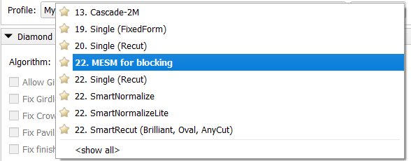
The usage of the new algorithm is very similar to “20. MEC for round bruting “:
- Choose "22. MESM for blocking" algorithms
- Select the SmartRecut solution for which you want to obtain enclosed symmetrical model
- Press “Start allocation”. You will receive a new solution with “Blocking_MESM” cutting title and “MESM” allocation mark:

The MESM algorithm is adjusted via presets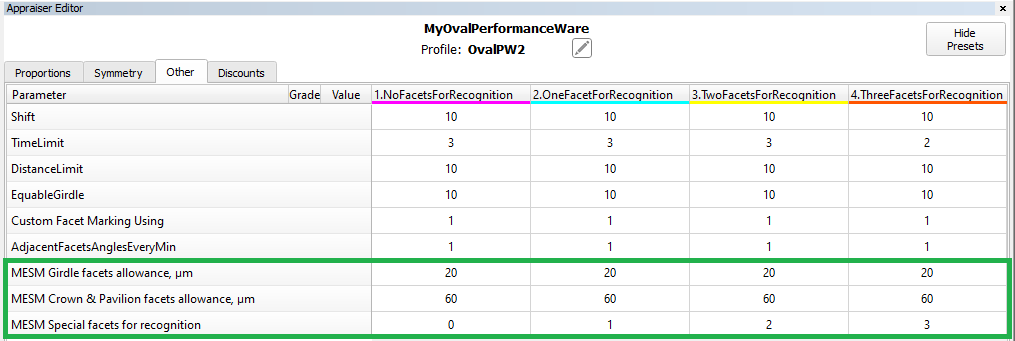
There are two allowances for Girdle facets and for Crown & Pavilion facets. It measured in microns. If necessary, they can be set to zero.
"MESM Special facets for recognition": in any case, on the crown and on the pavilion, one set of close facets selects in perpendicular directions. This parameter specifies the number of facets in sets
Methods of model building
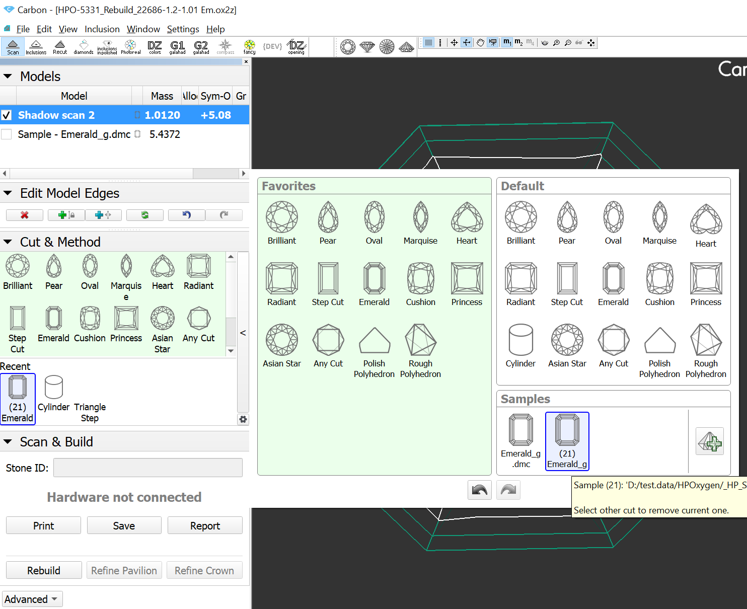
Method “Sample21”: new Model Building method by Sample
“Sample21”: new Model Building method with Sample.
To use this new building method you need to add a sample as usual with "Add sample button":
then two sample icons will appear: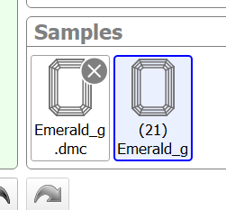
One is for classic Sample building method and another with "(21)" marker is for Sample21 building method.
Choose "(21)" -marked sample to use Sample21:
In-house cut workflow improvements
Compatibility of in-house cuts and linked appraisers between HP Carbon and Helium Rough/Pacor Client
Currently some allocation algorithms exists only in Helium Rough/Pacor Client but not in HP Carbon. Mainly there are semi-automatic or manual algorithms, that are available in Tools mode (like "Fixed Diamond Weight", "Change cut" and so on).
Therefore the same project is need to be open in both programs (HP Carbon and HR/PC) and compatibility of cuts and appraisers is required for work convenience.
Previously registered in HP Carbon Cuts and linked Appraisers are automatically loaded to Helium Rough since version 7.4 if Helium Rough is installed on the same computer.
Hybrid Appraisers (with Absolute and Relative parts) has limited compatibility:
- Helium Rough program version 7.4 doesn't have option to enable/disable Absolute and Relative parts.
- There is no convenient switch between profiles
Helium Rough will allocate with the same conditions of hybrid appraiser like they was during exit from HP Carbon. Under conditions we mean absolute, relative parts and profile .
Example of work:
Suppose we have following list of in-house cuts in HP Carbon:
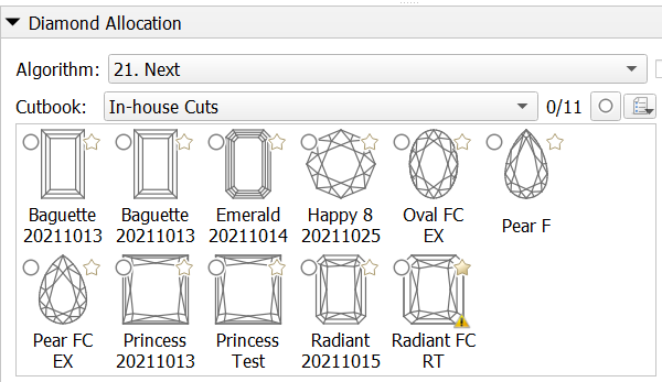
When we run Helium Rough then the same cuts will be available in panel Diamond.
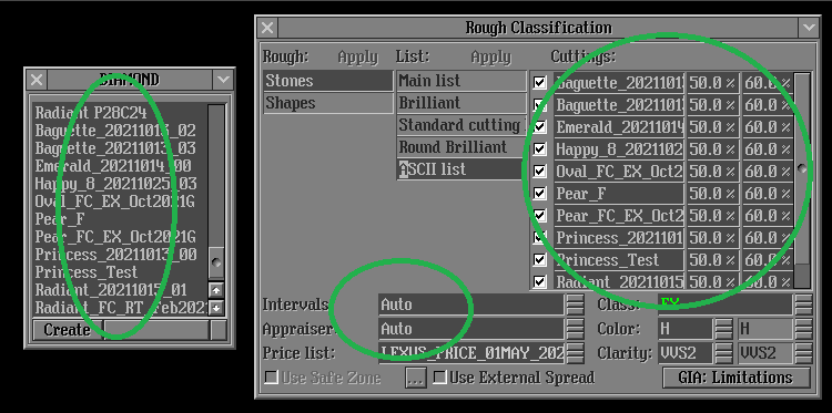
To run allocation with in-house cuts it is required:
- To create new list in Rough Classification panel and add necessary in-house cuts there.
- Select Intervals/Appraiser Auto.
Auto Appraiser allows to run allocation with several cuts and their linked different appraisers.
Usability upgrade of "MyAnyCut" appraiser presets for in-house cuts
To simplify navigation, the parameters in MyAnyCut presets are sorted into groups with the addition of prefixes in the names: "Girdle_", "Angles_", "Distances_", "ExtraFacets_"
Integrated documentation is connected for all parameters of the "Girdle_" group.

If you need to reduce the Area Loss of the SmartRecut solution, then decrease the Girdle_PointsAxialSymmetryIdeality via presets and restart the optimization.
Some exceptions are described in the integrated documentation Girdle_PointsAxialSymmetryIdeality or under ![]() in program.
in program.
Inclusions mode
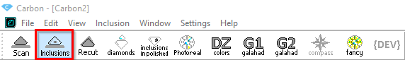
Now you can plot cavities manually on your model using the new ![]() Inclusions mode. To switch to the Inclusions mode, on the top panel, click
Inclusions mode. To switch to the Inclusions mode, on the top panel, click ![]() Inclusions.
Inclusions.
The following scenarios can be implemented in this mode:
- Plot cavities in live mode
- Plot cavities via photo sets
- Quickly prepare quality photo(s) of your rough
See details in the sections below.
Plot cavities in live mode
To plot cavities in live mode:
- Prerequisites: Shadow scanner is connected
- Scan your semipolished diamond, then go to Inclusions mode.
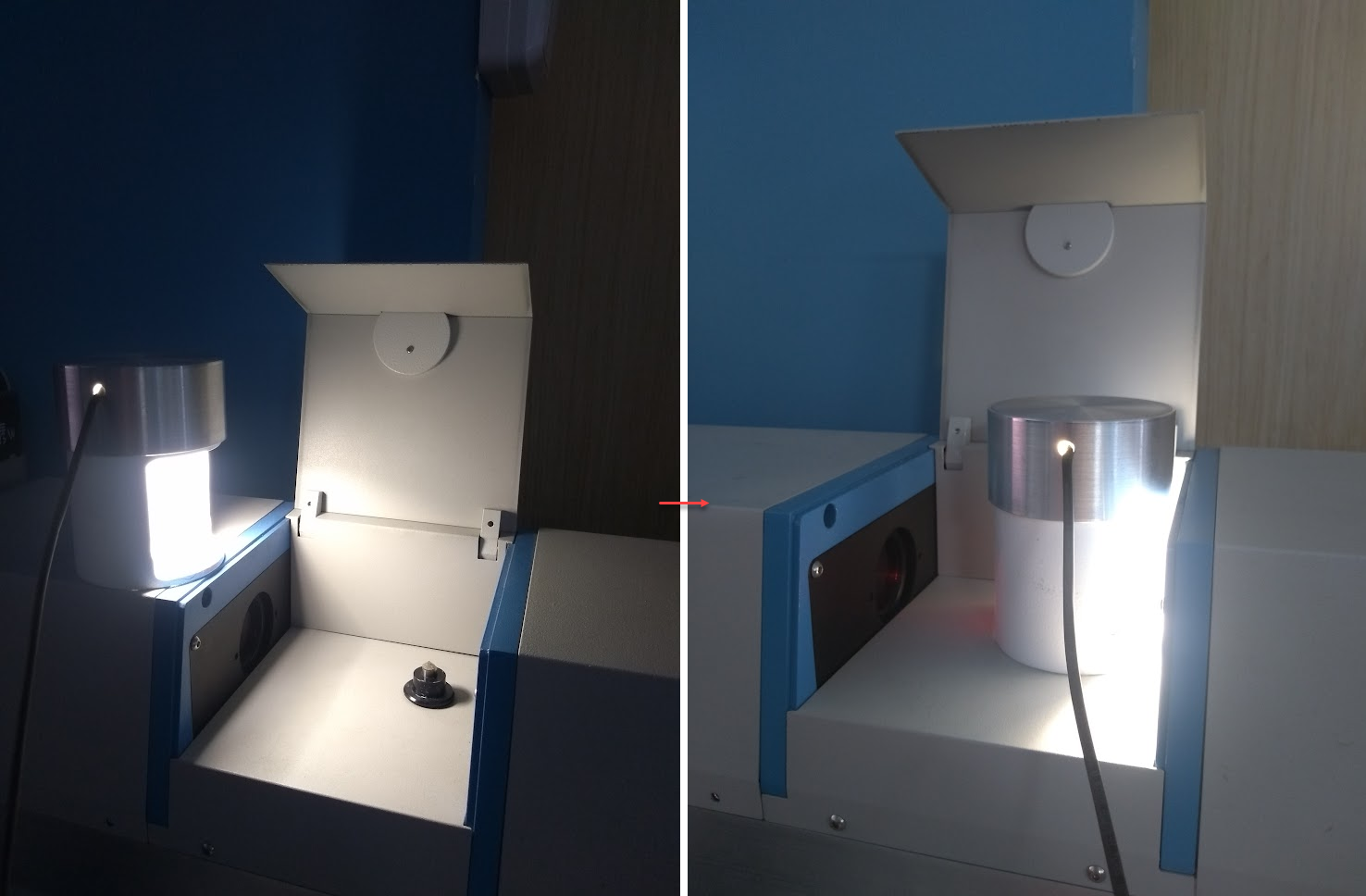
- In your scanner (hardware), change the lighting.
- In the Inclusions mode, "live camera" Mode, adjust the Camera (specifically, exposure Exp.) and Lighting settings to have the best view of your diamond.
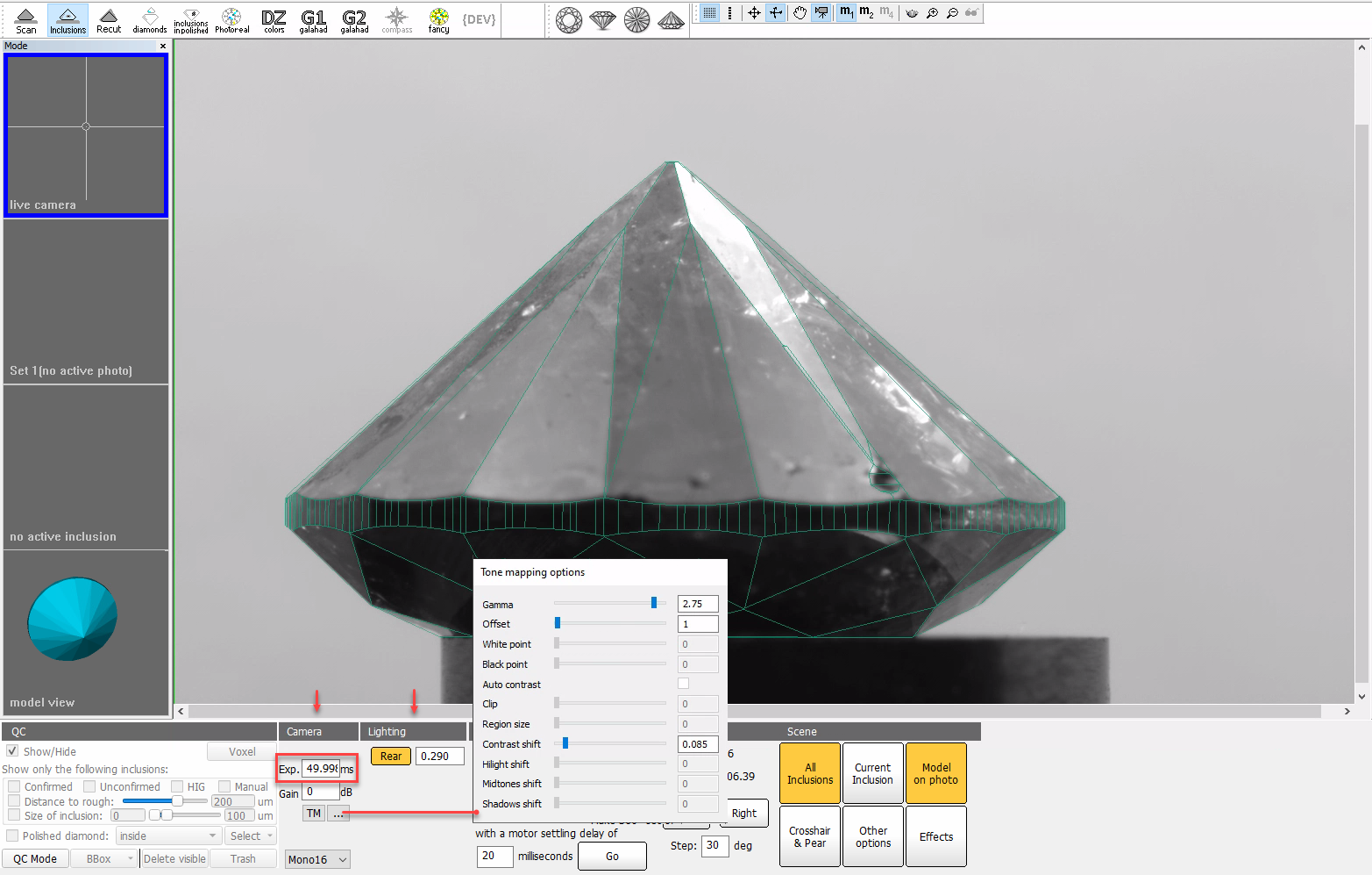
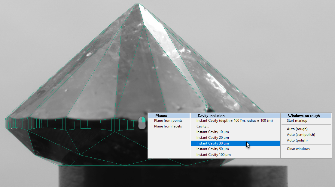
- Rotate your diamond via mouse drag, and then above the "live camera" view of it, for your model, add cavities and adjust facets using Boundary Plane Tool.
- Save your project.
Plot cavities via photo sets
| Note | ||
|---|---|---|
| ||
In the following description, 2 operators are acting - this is optional, all the activities described may be performed by the same operator. |
To plot cavities via photo sets:
- Operator 1:
- Prerequisites: Shadow scanner is connected on the first stage (not needed on the second)
- Scan your semipolished diamond, then go to Inclusions mode.
- In the Inclusions mode, "live camera" Mode, you adjust the Camera and Lighting settings to have the best view of your diamond.
- Make a new 360° photo set.
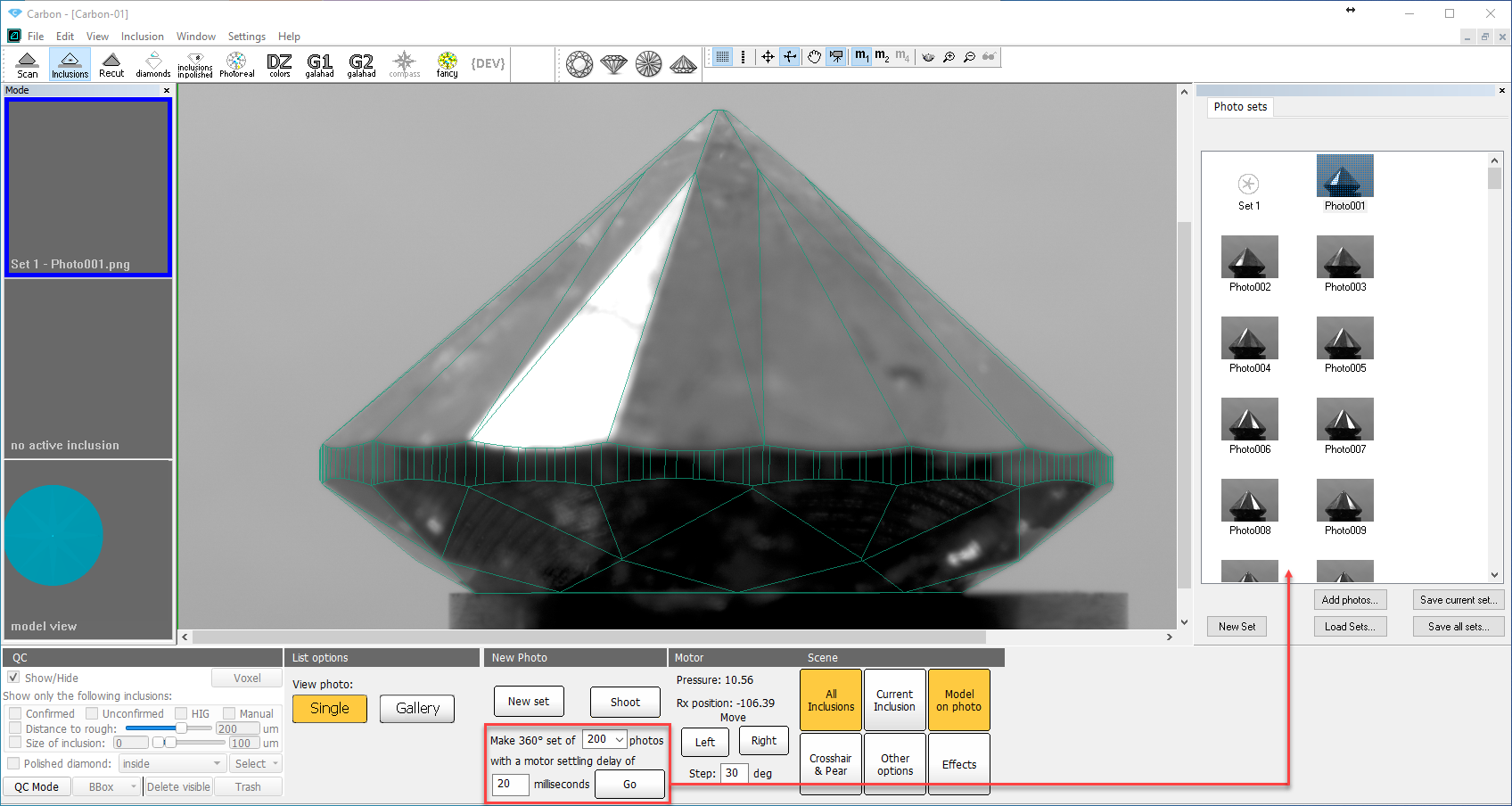
- Save your project along with the photo set and send them to Operator 2.
- Operator 2:
- In HP Carbon, open the project, go to Scan mode.
- On the right panel, use the Photos section to open the photo set.
- Go to Inclusions mode, use photo Mode.
- Rotate your model via mouse drag, and then above its "lifelike" view, for your model, add cavities and adjust facets using Boundary Plane Tool.
- Save your project.
Quickly prepare quality photo(s) of your rough
To quickly prepare quality photo(s) of your rough:
- Prerequisites: Shadow scanner is connected
- Go to Inclusions mode.
- In the Inclusions mode, "live camera" Mode, you adjust the Camera and Lighting settings to have the best view of your rough.
- Shoot any number of photos or photo sets.
- Save photo sets to disk.
- If necessary, use any tool to convert series of images into a video for a "motion" presentation of your rough.
Handy change of clarity or status of inclusions from scene
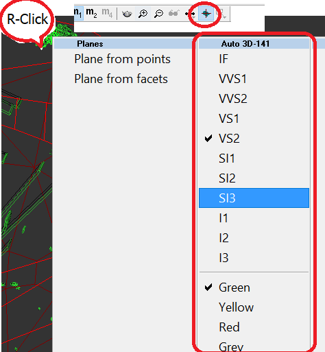
There is option to change clarity or status of inclusions from scene by two clicks:
- Go to "Recut" mode.
- Activate tool of inclusion selection in the main top menu of program.
- Right click on inclusion and you will see context menu where you can tick clarity and optimization status (color of inclusion - green. yellow, red, grey)
Holder replacement in a scanner
Holder deterioration requires it's replacement sometimes to get correct results of scanning. Now this procedure is accessible for users with special "Alignment" license bought from supplier.
You can order brand-new holders from scanner supplier too.
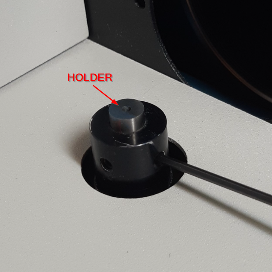
A procedure of holder change is described in Manual about holder change.
| Note | |||||
|---|---|---|---|---|---|
To use this functionality all the conditions should be met:
|
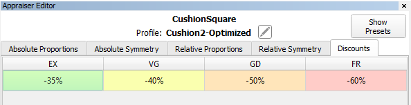
Cut Quality groups discounts
There are price discount for cut quality groups defined in appraiser. Initial discount that we provide "from a box" may not correspond actual market demand and specific customer needs.
There is a new Discount tab to edit discounts for Cut Quality groups (EX, VG, GD etc.) in Appraiser Editor panel:
Example
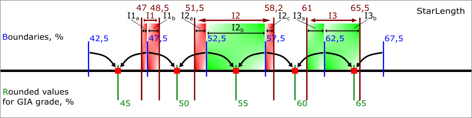
Let's take a look at StarLength as an example. For StarLength "recommended cell size" = 1.25%. There are 3 MyRound intervals in the figure
Interval I1 = [47, 48.5] is problem. It contains two red cells I1a = [47, 47.5] of length 0.5% and I1b = [47.5, 48.5] of length 1%. Both are shorter than "recommended cell size" = 1.25%
Interval I2 = [51.5, 58.2] is bad. It contains two red cells I2a = [51.5, 52.5] of length 1% and I2c = [57.5, 58.2] of length 0.7%. And one full green cell I2b = [52.5, 57.5].
Interval I3 = [61, 65.5] is good. It contains two green cells I3a = [61, 62.5] of length 1.5% and I3a = [62.5, 65.5] of length 3%. Both are longer than "recommended cell size" = 1.25%. If you reduce I3 to [61.3, 65.5] it becomes bad. If you reduce it to [61.3, 63.7] it becomes problem
Dead Zone and Safe Boundaries
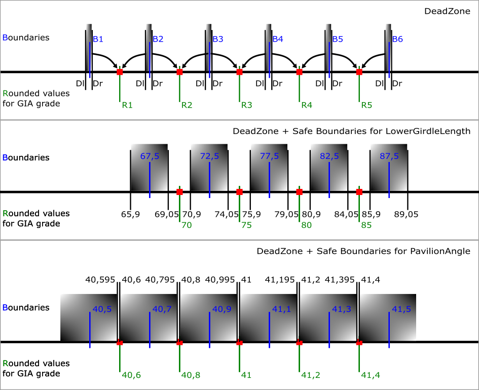
The current sizes of the dead zone are shown in the table. If you set narrow limits on the parameter in MyGIA, you must take into account the dead zone size and not fall completely into it.
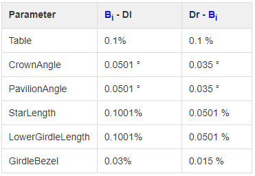
It is important to understand that the "Safe Boundaries" option will increase the size of the dead zone by margin. Below are the sizes of the dead zone in Safe Boundaries mode.
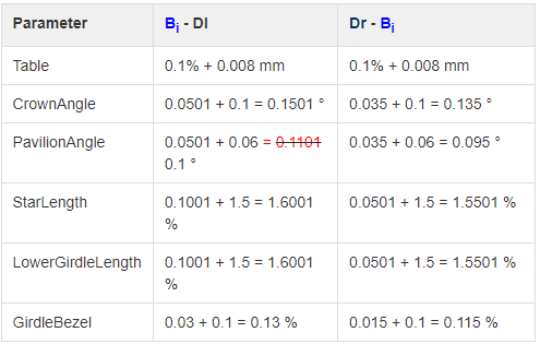
For example, in "Safe Boundaries" mode, you cannot require LowerGirdleLength exactly 71 or 72,73,74,76,77,78,79. Of the round values, only multiples of 5 are allowed.
Particular attention should be paid to the Pavilion Angle parameter. Its dead zone in "Safe Boundaries" mode occupies almost the entire space. Moreover, there is still a small chance that a GIA Cut grade error will be detected with margin = 0.06. For this parameter, Smart Recut can only technically guarantee safety when Margin < 0.049 (because of red equality in the table)
Precise fixation of parameters StarLength and LowerGirdleLength in SmartRecut (Brilliant)
StarLength and LowerGirdleLength are parameters that greatly affect the pattern of the stone, but practically do not affect the mass. Sometimes there is a need to get a specific average value for these parameters. Now you can do this by setting an interval of 0.02 length in MyRound. SmartRecut solutions will have the value exactly in the center of the interval. However, when setting narrow boundaries, it is necessary to take into account the dead zone, especially when working in Safe Boundaries mode. You can find out more information on the new documentation page Recommendations on Boundaries for main GIA parameters
SmartRecut + Safe Boundaries upgrade
There are two errors when grading diamonds obtained from SmartRecut solutions by GIA. First — the scanned on different scanners model may slightly deviate. Second — GIA before rounding uses a peculiar way of parameters averaging instead of the usual mathematical averaging. But SmartRecut can only use usual mathematical averaging. In the previous version both errors was including in Safe Boundaries margin. Therefore, if we added the full margin to the solution Math values then it was ok. But if we added the full margin to the solution GIA values, then it was possible to go beyond the GIA Cut grade.
In the current version Safe Boundaries margin is responsible only for the possible scanner error. And SmartRecut separately takes into account GIA rounding error (dead zone). So you can add the full margin to the solution GIA values, it will be ok.
Reports improvements
New report type - Rough Report
Objective
A manager receives a batch of stones, these each are in their own package. A Rough Report is printed in a small size and applied to a package with a stone.
The Rough Report is needed so that the manager can quickly check what was expected to do with the stone not opening its package.
Controlled diamonds' parameters: weight, cut quality, appraisers, Crown and Pavilion angles, etc.
Creation of Rough Report
- An operator sets the starting position of the stone in the HP Carbon scene for further an image generation.
The main scan or a solution could be rotated. Stone position in Rough Report is synchronized with the HP Carbon Scene.
- The operator selects the solution to be made in the Plans & Scans panel.
- The operator can select diamonds to be included into the report.
All diamonds are shown in Rough Report by default. Diamonds could be added or removed in opened report it will be updated in this case.
This is done using the context menu in the panel containing diamonds info for the current solution.
- Open Rough Report panel.
- Selection of a printer. The selected printer is saved in HP Carbon and will be shown at further openings of Rough Report.
- Print the Rough Report.
Rough Report features
The operator can change colors in Rough Report (Rough, Model, Saw, Inclusions). It will be updated at a color changing.
Also enhanced precision could be changed in the range [-3, 3] digits. The report will be updated at an enhanced precision changing.
All settings are saved in HP Carbon.
The Rough Report will be updated at selection of another solution.
![]() Inclusions while aren't embedded in Rough Report images.
Inclusions while aren't embedded in Rough Report images.
Illustrated HTML Report templates for many other cuts are available (besides RBC)
The convenient single-page reports in HTML format have been made for most types of cuts (as was previously done for RBC), so that the operator, without the need to use MS Word, could open the main parameters of the model on the screen on one page and transfer them to the clients/auditor/manager:
- Polished HTML Illustrated Report Step Cut;
- Polished HTML Illustrated Report Radiant;
- Polished HTML Illustrated Report Square Radiant;
- Polished HTML Illustrated Report Triangle;
- Polished HTML Illustrated Report Rounded Fancies;
- Polished HTML Illustrated Report Oval-Marquise.
These reports are located in "Polish Report..." for a specific type of cuts, for an example:
Examples of reports:
1) Illustrated HTML Report Step Cut
2) Illustrated HTML Report Radiant
3) Illustrated HTML Report Square Radiant
4) Illustrated HTML Report Triangle
5) Illustrated HTML Report Rounded Fancies
6) Illustrated HTML Report Oval&Marquise
View grades for Cushion cuts in reports
For the Rectangular and Square Cushion cuts the grades were added to the following reports:
- Standard report
- HTML Illustrative report
- RTF Illustrative report
- Label report
Some minor layout changes were caused by this change (shorten parameter names and display positions.
...
...
View with and length for lengthened cuts
Information about the width, length, and girdle ratio is added to:
- Label and Semipolish reports for all cuts.
- Standard reports for all cuts except Brilliant.
Algorithms of allocation
New algorithm "21. Next" for allocation
To add one more diamond to already created solution you can use algorithm "21. Next". The next diamond will be added in maximal possible free zone of rough volume which is not occupied by created before diamonds. A position of existing diamonds is not changed.
Important! Algorithm "21. Next" during work takes into account allocation forms of Cut that allows to find better solutions for in-house cuts. Note that algorithm Find Next Diamond in Helium Rough / Pacor Client doesn't work with many allocation forms so we recommend to use "21. Next" and HP Carbon to find next diamond.
...
0012_NextDiamond.ox2z
Sol. #40 contains 5 diamonds, it was allocated sequentially from sol. #24, 30, 34.
New algorithm "22. MESM for blocking"
We have implemented a new algorithm: Minimum Enclosing (Encompassing) Symmetrical Model - "22. MESM for blocking"
The algorithm finds the Minimum Enclosing Symmetrical Model. Then inflates this model by 100 microns. Then it offsets 3 adjacent faces on the pavilion and on the crown, which are in almost perpendicular directions. From these faces, you can determine the orientation of the model after blocking in the space of the SmartRecut solution.
New algorithm is available in the allocation algorithms as a new line "22. MESM for blocking":
The usage of the new algorithm is very similar to “20. MEC for round bruting “:
...
There are two allowances for Girdle facets and for Crown & Pavilion facets. It measured in microns. If necessary, they can be set to zero.
"MESM Special facets for recognition": in any case, on the crown and on the pavilion, one set of close facets selects in perpendicular directions. This parameter specifies the number of facets in sets
Methods of model building
Method “Sample21”: new Model Building method by Sample
“Sample21”: new Model Building method with Sample.
To use this new building method you need to add a sample as usual with "Add sample button":
then two sample icons will appear:
One is for classic Sample building method and another with "(21)" marker is for Sample21 building method.
Choose "(21)" -marked sample to use Sample21:
In-house cut workflow improvements
Compatibility of in-house cuts and linked appraisers between HP Carbon and Helium Rough/Pacor Client
Currently some allocation algorithms exists only in Helium Rough/Pacor Client but not in HP Carbon. Mainly there are semi-automatic or manual algorithms, that are available in Tools mode (like "Fixed Diamond Weight", "Change cut" and so on).
Therefore the same project is need to be open in both programs (HP Carbon and HR/PC) and compatibility of cuts and appraisers is required for work convenience.
Previously registered in HP Carbon Cuts and linked Appraisers are automatically loaded to Helium Rough since version 7.4 if Helium Rough is installed on the same computer.
Hybrid Appraisers (with Absolute and Relative parts) has limited compatibility:
- Helium Rough program version 7.4 doesn't have option to enable/disable Absolute and Relative parts.
- There is no convenient switch between profiles
Helium Rough will allocate with the same conditions of hybrid appraiser like they was during exit from HP Carbon. Under conditions we mean absolute, relative parts and profile .
Example of work:
Suppose we have following list of in-house cuts in HP Carbon:
When we run Helium Rough then the same cuts will be available in panel Diamond.
To run allocation with in-house cuts it is required:
- To create new list in Rough Classification panel and add necessary in-house cuts there.
- Select Intervals/Appraiser Auto.
Auto Appraiser allows to run allocation with several cuts and their linked different appraisers.
Usability upgrade of "MyAnyCut" appraiser presets for in-house cuts
To simplify navigation, the parameters in MyAnyCut presets are sorted into groups with the addition of prefixes in the names: "Girdle_", "Angles_", "Distances_", "ExtraFacets_"
Integrated documentation is connected for all parameters of the "Girdle_" group.
If you need to reduce the Area Loss of the SmartRecut solution, then decrease the Girdle_PointsAxialSymmetryIdeality via presets and restart the optimization.
Some exceptions are described in the integrated documentation Girdle_PointsAxialSymmetryIdeality or under ![]() in program.
in program.
Inclusions mode
Now you can plot cavities manually on your model using the new ![]() Inclusions mode. To switch to the Inclusions mode, on the top panel, click
Inclusions mode. To switch to the Inclusions mode, on the top panel, click ![]() Inclusions.
Inclusions.
The following scenarios can be implemented in this mode:
- Plot cavities in live mode
- Plot cavities via photo sets
- Quickly prepare quality photo(s) of your rough
See details in the sections below.
Plot cavities in live mode
To plot cavities in live mode:
...
Plot cavities via photo sets
| Note | ||
|---|---|---|
| ||
In the following description, 2 operators are acting - this is optional, all the activities described may be performed by the same operator. |
To plot cavities via photo sets:
...
Quickly prepare quality photo(s) of your rough
To quickly prepare quality photo(s) of your rough:
- Prerequisites: Shadow scanner is connected
- Go to Inclusions mode.
- In the Inclusions mode, "live camera" Mode, you adjust the Camera and Lighting settings to have the best view of your rough.
- Shoot any number of photos or photo sets.
- Save photo sets to disk.
- If necessary, use any tool to convert series of images into a video for a "motion" presentation of your rough.
Handy change of clarity or status of inclusions from scene
There is option to change clarity or status of inclusions from scene by two clicks:
- Go to "Recut" mode.
- Activate tool of inclusion selection in the main top menu of program.
- Right click on inclusion and you will see context menu where you can tick clarity and optimization status (color of inclusion - green. yellow, red, grey)
Holder replacement in a scanner
Holder deterioration requires it's replacement sometimes to get correct results of scanning. Now this procedure is accessible for users with special "Alignment" license bought from supplier.
You can order brand-new holders from scanner supplier too.
A procedure of holder change is described in Manual about holder change.
...
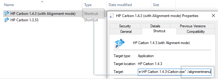
To use this functionality all the conditions should be met:
- You should use the system with HASP key with "Alignment" option,
- The system should be launched by the shortcut of Carbon.exe with the "/alignmentmenu" flag.
| Expand | ||
|---|---|---|
| ||
|
Cut Quality groups discounts
There are price discount for cut quality groups defined in appraiser. Initial discount that we provide "from a box" may not correspond actual market demand and specific customer needs.
There is a new Discount tab to edit discounts for Cut Quality groups (EX, VG, GD etc.) in Appraiser Editor panel:
Get symmetrical solutions in spite of mistakes in facet types
To increase model symmetry and remove excess facets, you can use the Smart Normalize algorithm. Previously, if the model that you were going to normalize had mistakes in its facet types, Smart Normalize could provide non-symmetrical solutions. Now the algorithm is improved: it tries to fix mistakes in facet types and then provides excellent symmetry.
Hint This is especially useful when mistakes are not obvious to an operator.
Technical details:
- The algorithm tries to fix facet type mistakes using information about groups of symmetrical facets and which type dominates in a group. If the situation is clear enough, mistakes in facet types are fixed automatically and the algorithm finds the solution with the correct number of symmetry axes. If the case is too complex, the algorithm uses initial facet types without changes.
- Fixing does not change the initial model facet types but does change the resulting model - it will have different (fixed) facet types.
Example:
...
...
...
...
Get plans for Brilliant cut that are safe from perspective of GIA cut grade
In HP Carbon, plans for Brilliant cut are allocated with the "GIA Facetware + My Round" appraiser. GIA Facetware rounds the parameters' values.
In some cases, this rounding may cause a problem: when you finish cutting in precise accordance with the plan and the result is scanned, different scanners (for example, yours and GIA lab) may slightly deviate the scanned model. So if our plan was too close to rounding boundaries, the resulting parameter value after rounding may go outside the EX boundaries to VG, etc. This can cause your EX stone from your scanner perspective will unexpectedly become VG from the GIA lab perspective.
To eliminate this risk, for the Smart Recut algorithm, the new Safe Boundaries mode is added. It is intended to be used when working with Brilliant cut. The mode sets safe distances to a possible GIA rounding. The values are:
...
| title | Example for Crown Angle |
|---|
...
...
...
| Note |
|---|
At the moment, these values cannot be changed - in the future, it is planned to provide a user interface for viewing/editing. |
The mode is turned on by the Safe Boundaries checkbox.
The mode can be used when running the Smart Recut allocation from Recut solution. However, if you already have a Smart Recut solution previously obtained without using the Safe Boundaries option, it is more effective to run Smart Recut allocation with Safe Boundaries from this previous Smart Recut.
...
Fancy Color workflow improvements
...
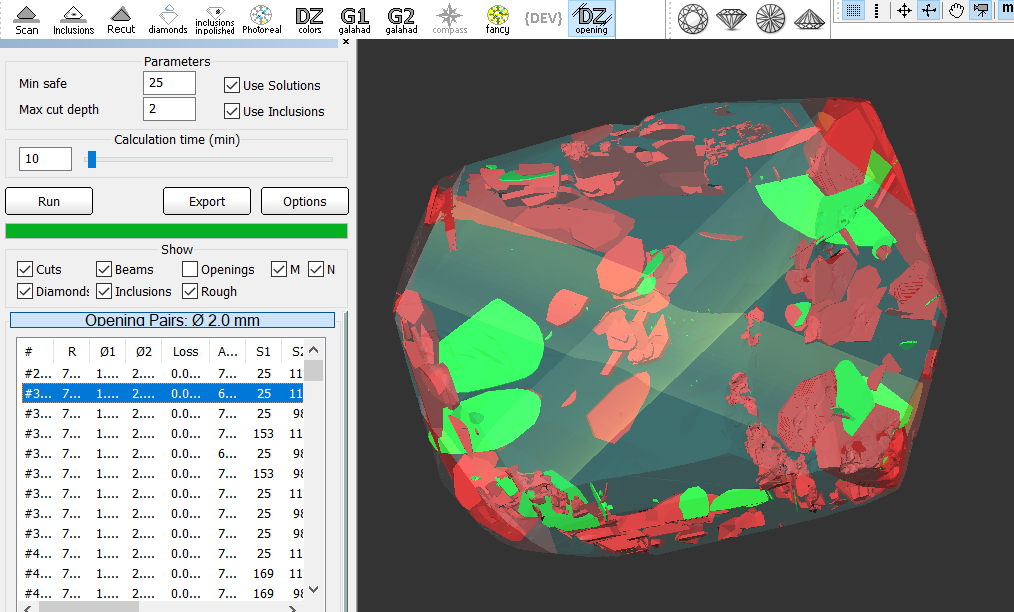
The function of the Openings mode is similar to former "Oxygen DZ" software.
Control absolute value azimuths for in-house cuts
In previous versions, for in-house cuts the algorithm 19. SmartRecut (Brilliant, Oval, AnyCut) controlled only the azimuths symmetry of the facets. But a change in the absolute value of azimuths could lead to a big loss of the solutions performance.
Therefore two parameters have been added to control the tolerance of azimuths from the initial values. More "narrow" MainAzimuthsToleranceModule is tuned for only Main facets. Less "narrow" OtherAzimuthsToleranceModule is tuned for other facets.
Get corrected color estimation for diamonds with fluorescence
...