HP Carbon has an intuitive interface with a lot of features helping users to solve everyday tasks.
HP Carbon Window
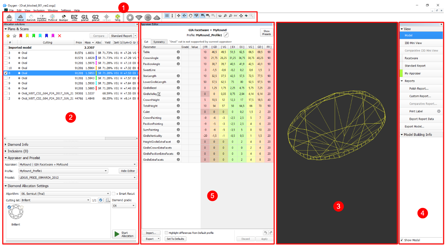
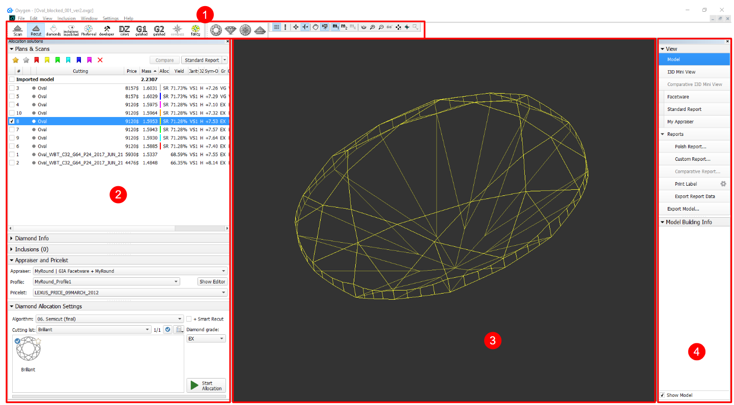
The program window is divided into the following areas:
- Top panel
- Left panel
- Scene
- Right panel
- (Optional) Additional panels
Besides that, some features are set up in additional pop-up windows.
Below are the examples of how the main window may look with or without additional panels:
Top Panel

The top panel includes several sub-panels:
- Main panel
Buttons for stone standard positions
Toolbox
Main Panel
The Main Panel determines the mode of operation with the following possible values:
- Scan. Left panel changes to Scan & Build (see below) which can be used to adjust the model (see Model Adjustment ) and to control the hardware if any (see Scanning ). The wireframe model is shown in the Scene.
- Recut. Left panel changes to contain Plans & Scans (see below) (see Models management ) and the features related to recut (see Smart Recut ) and appraising (see GIA Facetware ). The wireframe model is shown in the Scene.
- Diamonds. Left panel changes to Plans & Scans. The model in the Scene changes to the shaded view.
- Inclusions. Left panel changes to Plans & Scans. The Scene is split into two horizontal sub-fields to show inclusions in the polished diamond.
- Photoreal. Left panel changes to Plans & Scans. The Scene is split into two horizontal sub-fields to show the wireframe model and the photorealistic view.
- Developer. The whole window changes to developer mode in order to provide more low-level control of hardware, photosets, etc.
- DZ colors. The whole window changes to DZ mode (see DZ color estimate).
- G1 Galahad. Left panel changes to the mode for managing next step plans for the selected plan (see G1 Galahad).
Buttons for Stone Standard Positions
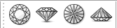
- Top View (Crown)
- Side View (Table Up)
- Bottom View (Pavilion)
- Side View (Table Down)
Toolbox
The buttons of the toolbox allow managing stone view in the Scene.
Left Panel
The left panel may operate in two modes:
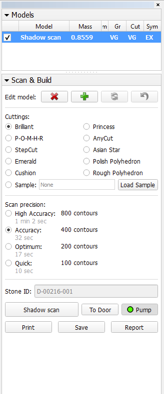
- Scan & Build can be used to control the hardware (see Scanning ) and to adjust the model (see Model Adjustment ).
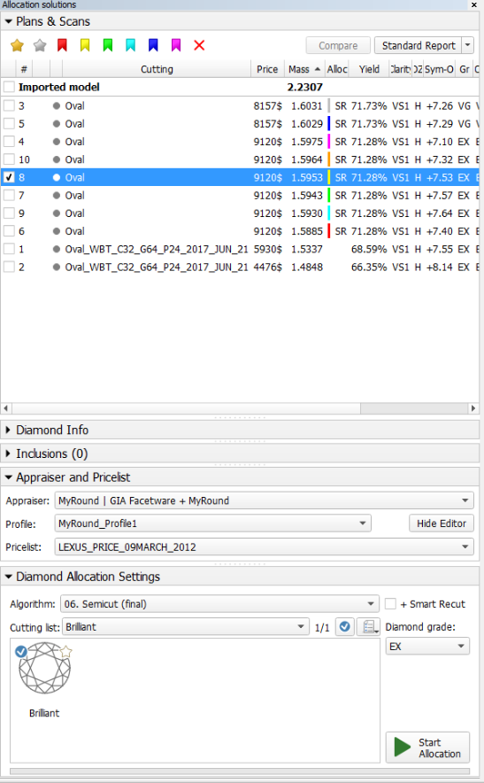
- Plans & Scans contains the features related to recut (see Smart Recut ) and appraising (see GIA Facetware ).
| Scan & Build | Plans & Scans |
|---|---|
 |
|
Note
The set of displayed columns for the scan/solution list is configurable. For details, see Configurable Set of Columns in Solution List.
Additional Panels
The following additional panels are available:
For more detailed description refer to the corresponding particular examples.
Additional panels may be repositioned by dragging their top bar. In particular, they may be stacked atop each other. The limitation of two simultaneously shown panels still applies in this case.
Scene
The Scene can work in the following view modes: Model, Photos, and Scanner. To switch between the modes, use the buttons on the right panel (see below).
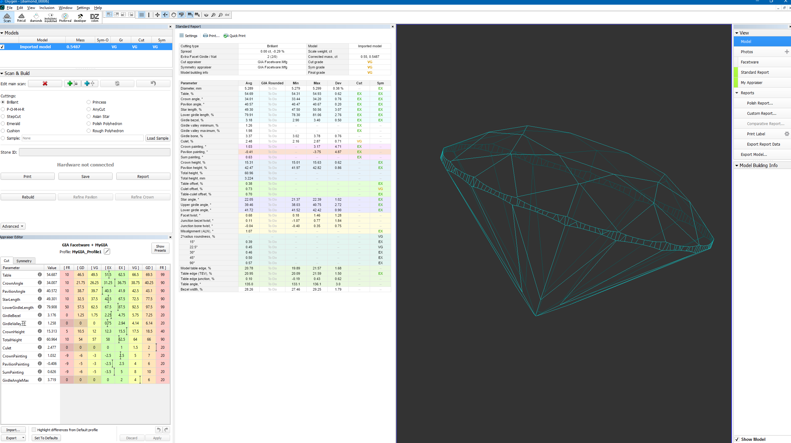
- Model view mode displays the model(s), if any (see Models management: Selecting models ). The model can be rotated in 3D by mouse dragging.
If there is no model, the field is displayed empty. - Photos view mode displays a photo from the current photoset with overlaid model, if any. The model can be switched off by the Show Model check box in the bottom part of the right panel. Dragging the mouse rotates the scene around the vertical axis and displays other photos taken from the corresponding angles.
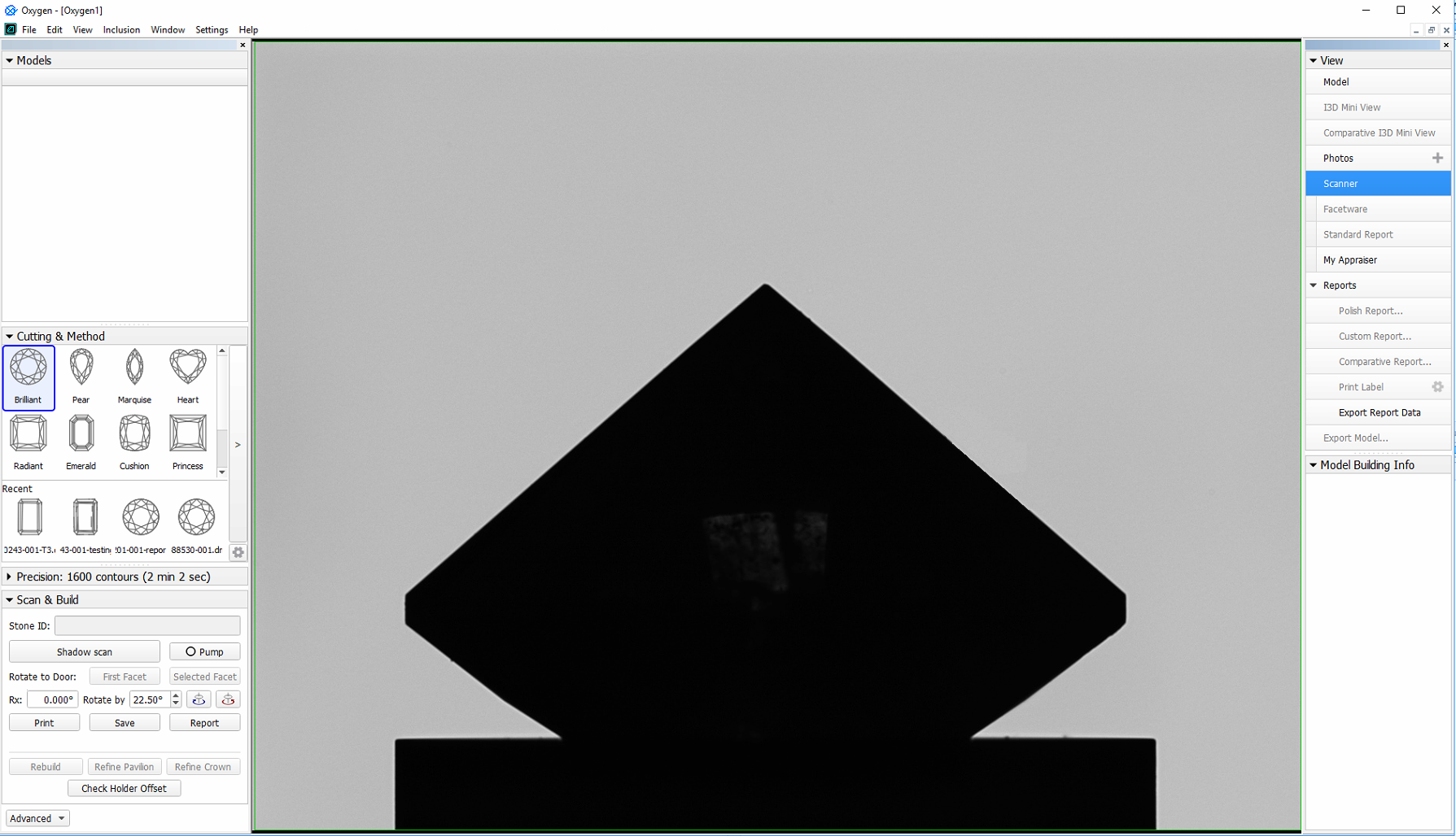
If no photoset is loaded, this mode is disabled. - Scanner view mode displays the live feed from the camera with overlaid model, if any. The model can be switched off by the Show Model check box in the bottom part of the right panel. Dragging the mouse rotates the real stone around the vertical axis.
If there is no hardware connected, this mode is disabled.
Note
For the Scene in Model or Photos view, you can show the grid. For details, see "Scene Model and Photos View - Show Grid Option" in Adjusting Interface.
Right panel
Right panel controls the additional panels and reports. It contains the following groups of elements:
|
|


Buttons that control additional panels (Facetware, Standard report, My Appraiser) have an indicator to the left which turns green when the corresponding panel is shown.
Special Modes
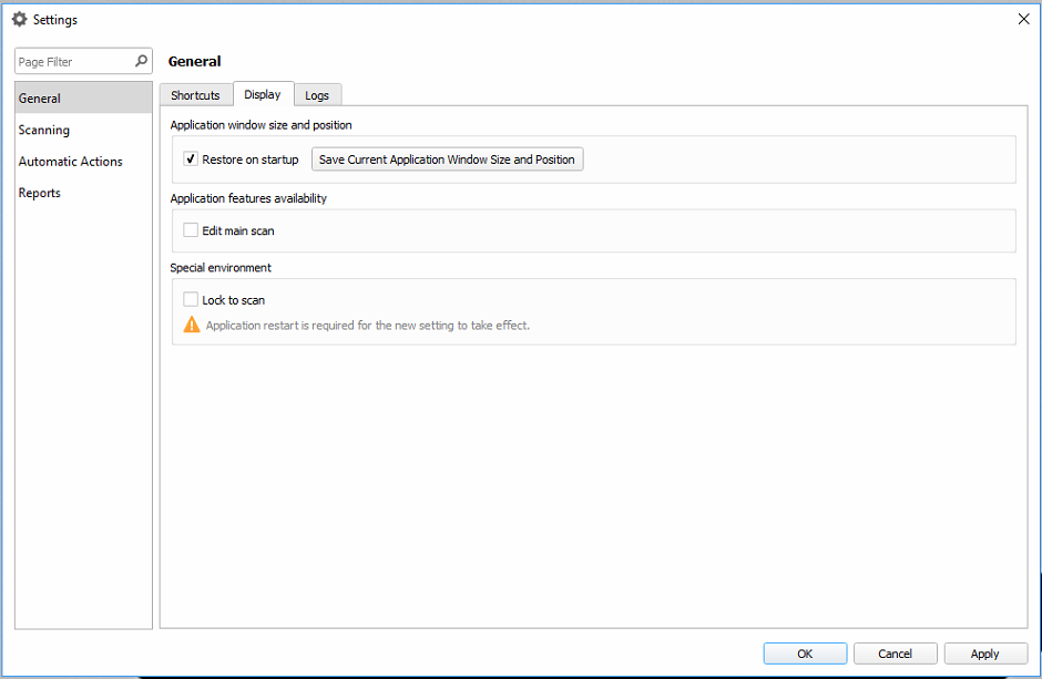
Lock to Scan
The Lock to scan option for the user interface is available. The option locks the system to the Scan & Build mode and hides the Top Panel along with all the buttons.
To enable the option, go to Settings > General Settings > General section > Display tab > in the Special Environment group, select Lock to scan.
Application restart is required for the new setting to take effect.