Here you can find information about what is new in HP Carbon version 1.1.33.
Creating "Sandwich" Inclusions
For the stones with inclusions, the system now supports the ability to increase in some cases the mass of the solution by specifying that some part of inclusion can be included in the future solution. This can be done by marking an inclusion as multi-part ("Sandwich").
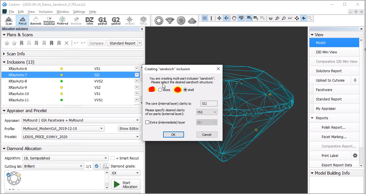
For a future "sandwich" inclusion you can specify:
- Desired structure: Slices (Recommended) or Shell.
- Desired clarity of the external layer compared to the internal layer clarity.
- Optionally - Extra (intermediate) layer presence and clarity.
To make an inclusion "sandwich":
- In the Recut mode, access the Inclusions panel.
- From the menu for your inclusion, select Make Sandwich. The Creating "Sandwich" Inclusion dialog is displayed.
- Specify the "sandwich" options and then click OK. In the Inclusions panel, your inclusion will be slit into the corresponding parts.
- Run optimization with your new inclusions.
You can find some details in the video below:
| Video | Increasing Mass - Using Sandwich Inclusions | ||||
| Published: | 2020, October 16 | Last Updated: | 2020, October 16 | v.2.0 |
| ||||
Video summary:
| ||||
Video keywords: clarity, inclusion, sandwich, QC panel | ||||
| Published in: | Release Notes | |||
| Documentation | Inclusions | |||
| Playlists | All Videos | YouTube: HP Carbon | |||
| Also | As Separate Page | On YouTube | Specification | |||
Scanning - Applying Facet Marking from Sample
Now during scanning using a loaded sample cutting, a facet marking from this sample is automatically transferred to the created 3D model. This provides an effective way of getting the correct facet classification (marking) for your model and creating the appropriate reports .
For example:
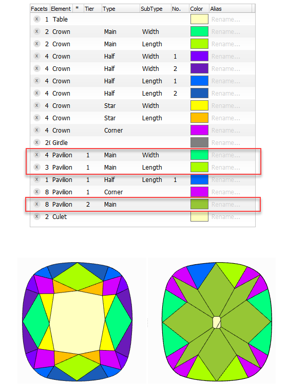
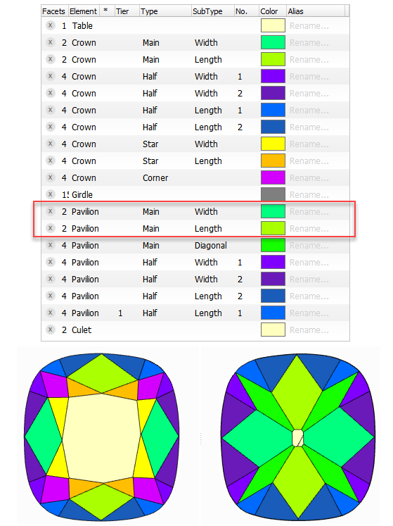
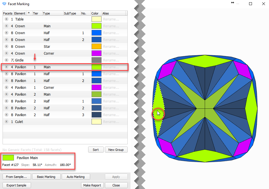
| Auto Marking | Marking of Sample and Resulting Marking (identical) |
|
|
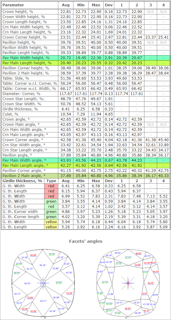
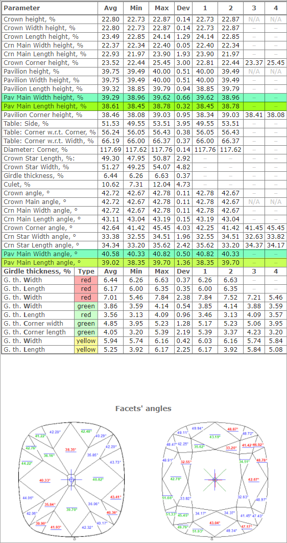
Resulting Polish Report (strings for Pav Main Width, Pav Main Length, and Pavilion 2 Main are highlighted with the colors from Facet Marking) | |
|
|
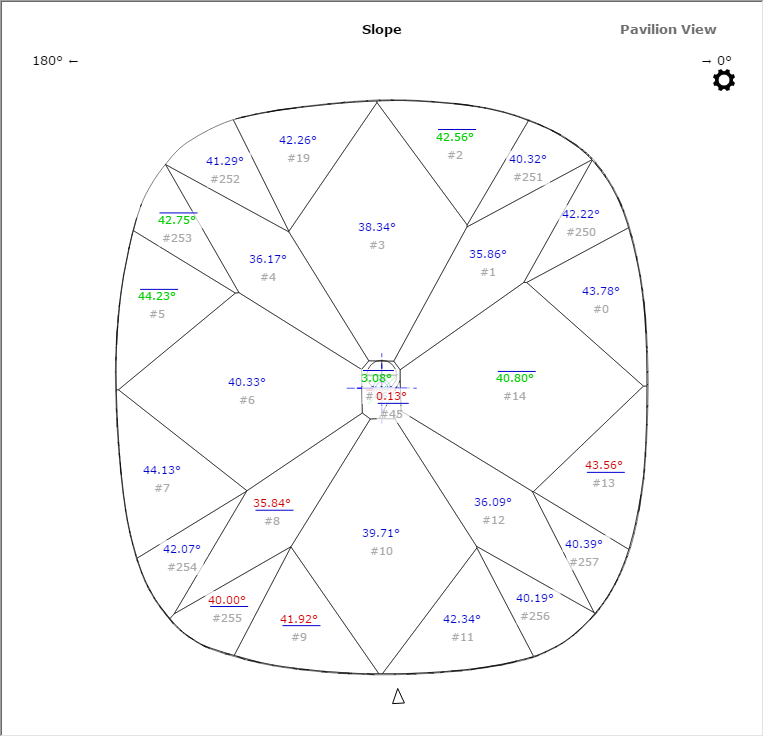
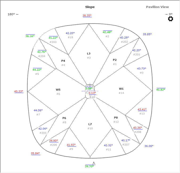
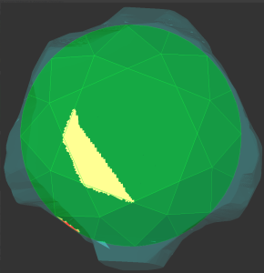
| Resulting I3D Pavilion View | |
|
|
- You can view the facet marking of your sample (DMC format). Do one of the following:
- As you select your sample in Cutting & Method, it is added to the Models section. There click its name, then on the right panel, click Facet Marking.
- Open your DMC in HP Carbon and then click the Facet Marking button on the right panel. The file can be opened by:
- Drag and drop your DMC to the HP Carbon window.
- In HP Carbon, select File > Open, navigate to your folder, then start typing the name of your file. As soon as it is suggested, select the file and click Open.
- You can change something in the facet marking of your DMC sample. To do this, perform the steps:
- Open DMC and its facet marking as described above.
- Make changes to the facet marking.
- Click Export Sample, specify a name for your changes version, and then click Save.
- Add a new version of the sample to the system, remove the old one.
Industrial Object Models - Build and Facet Marking Improvement
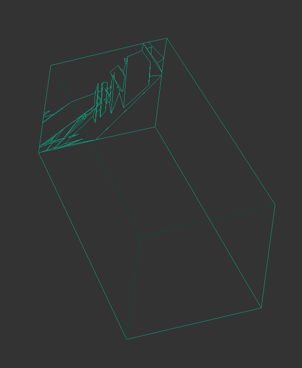
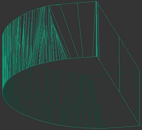
A building of industrial object models (cubes, cuboids, trapezoids, truncated cylinders) is improved.
| Was | Now |
|---|---|
|
|
|
|
|
|
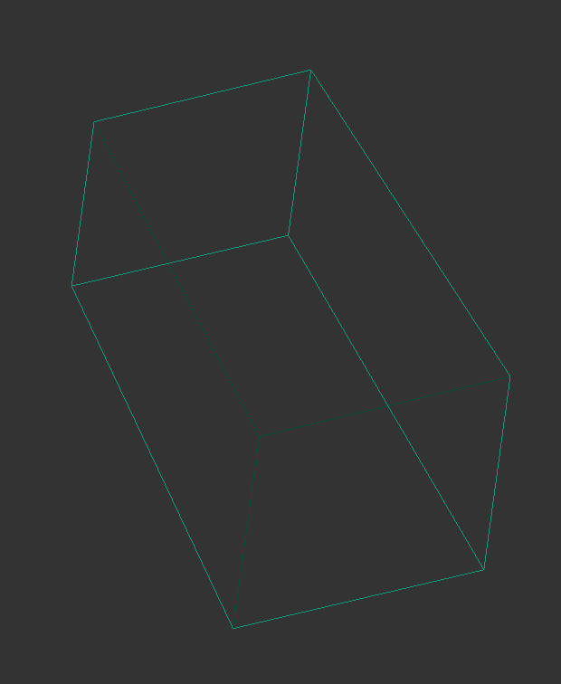
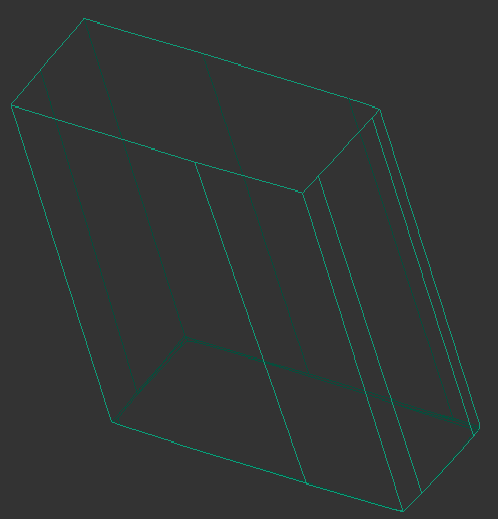
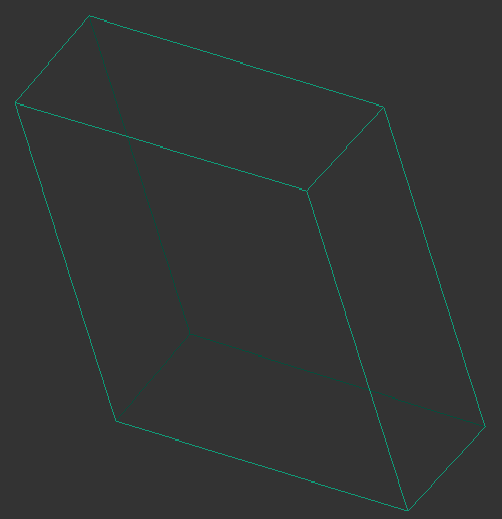
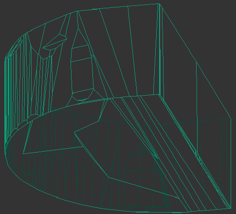
For such models, it is also necessary to apply a facet marking from your sample.
To build a good model for your simple object and automatically apply a facet marking from your sample to it:
- Prepare your DMC sample with the appropriate facet marking.
- Use the Scan mode.
- In the Cutting & Method section, add
 your sample to the list.
 - Select your sample as a cutting. The system will automatically set the optimal method.
- Start scanning.
The model of your object is built using one of the improved methods and added to the Models section. Its facet marking is automatically taken from your sample.
Trapezoid Workflow
Now you can use the system to quickly obtain important information ( report ) about your trapezoid-like objects:
What is improved and added to the system and for what?
| Type of Update | Feature | Description | Why that was not enough? |
|---|---|---|---|
| New | HTML illustrated report for trapezoid Described in this Release Notes in HTML Illustrated for Trapezoid | Gives you all the important parameters and pictures of your trapezoid model. | Before running the report, you need a good model with the appropriate facet marking. |
| Improved | Method of building the trapezoid-like models during the scanning Described in this Release Notes in Industrial Object Models - Build and Facet Marking Improvement | The methods used for building trapezoid-like models are improved: you do not obtain unnecessary extra facets any more, the model is more precise. | Problem 1: you need to think about which method to select. Problem 2: even the good model needs an appropriate facet marking - previously scans did not obtain facet marking automatically. |
| New | When scanning/rebuilding using the sample trapezoid:
Described in this Release Notes in Scanning - Applying Facet Marking from Sample | If during scanning/rebuild you use your own sample trapezoid as cutting, the appropriate method will be detected by the system automatically, and your good facet marking will be automatically transferred from sample to your scan. | This gives you all except the report - which was given is step 1! |
How to work?
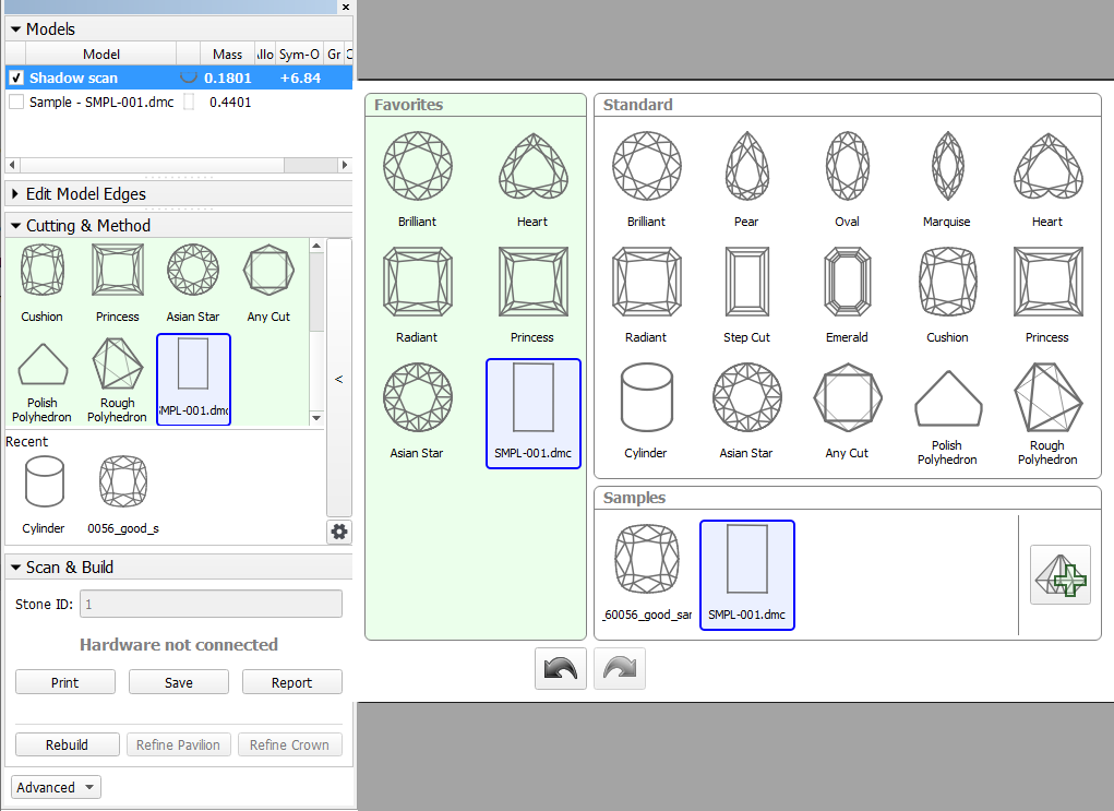
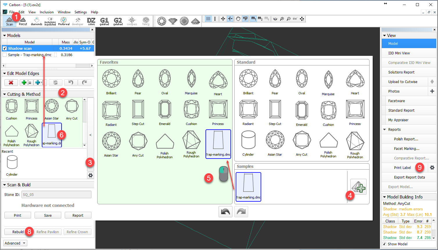
- Use the Scan mode.
- Use the Cutting & Method section.
- Expand the section.
- Add your sample.
- If necessary, drag your sample to the Favorites list.
- Select your sample to be used as cutting. The sample will be added to the Models section.
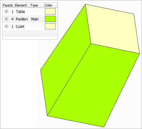
- To check the facet marking of your sample, in the Models section, click your sample, then on the right panel, click Facet Marking.
- Side facets of your trapezoid should be marked as "Pavilion - Main".
- If you want to modify the facet marking of your sample, in the Facet Marking dialog make your changes, then click Export Sample and save as DMC.
- You will need to add a changed version of the sample and then use it (repeat step 2).
- Remove the old sample from the Samples list.
- Run Scan or Rebuild. Your new scan is added to the Models section.
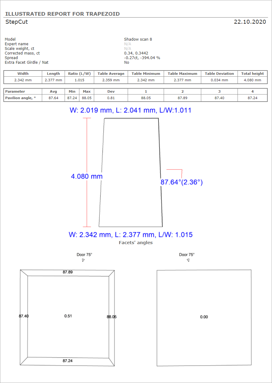
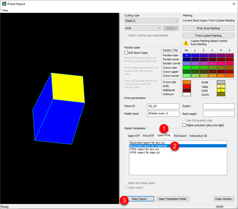
With your new scan selected, on the right panel, click Polish Report, go to Open HTML, then select "Illustrated report for trapezoid" and Make Report.
Polish Report Templates
HTML Illustrated for Trapezoid
The new template for Polish Report is added - HTML Illustrated for Trapezoid.
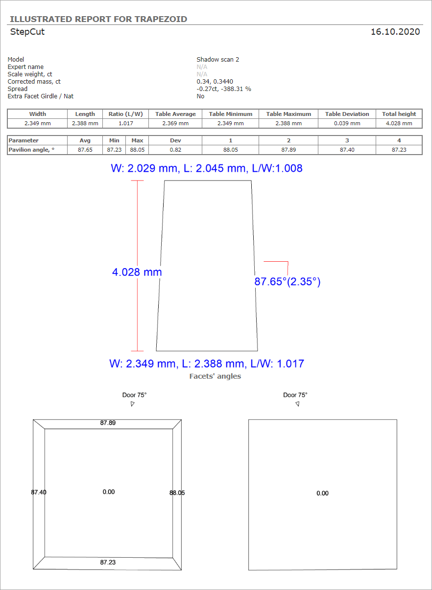
This template is an essential part of the Trapezoid Workflow.
Square Cushion - Cutting Type Support and Reports
Now in Polish Report, the Cutting Type list includes "Square Cushion".
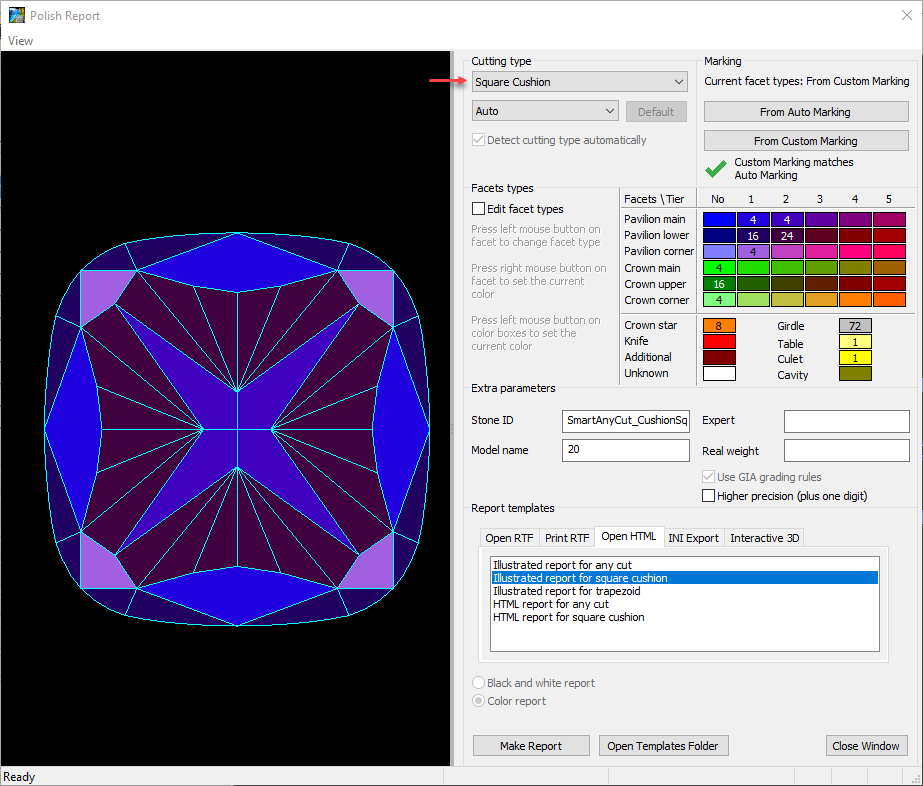
The following report templates are added for this cutting type:
- HTML
- Illustrated report for square cushion
- HTML report for square cushion
- I3D
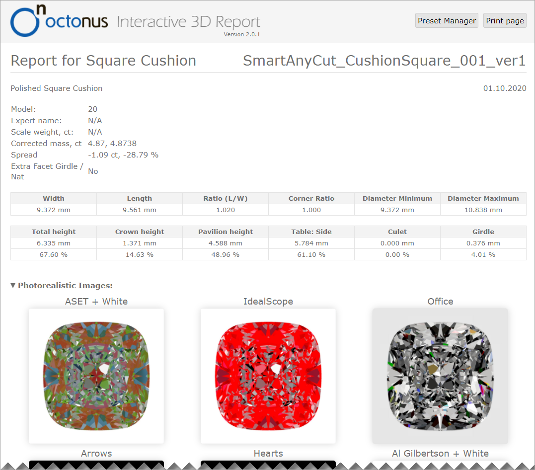
Also, the Standard Report for Square Cushion is updated correspondingly.
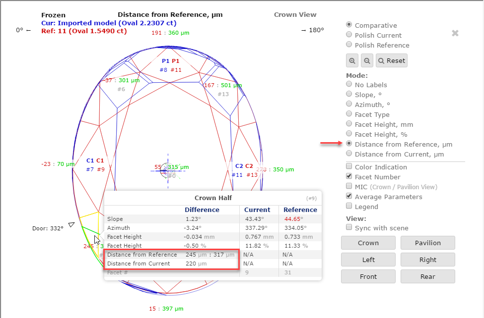
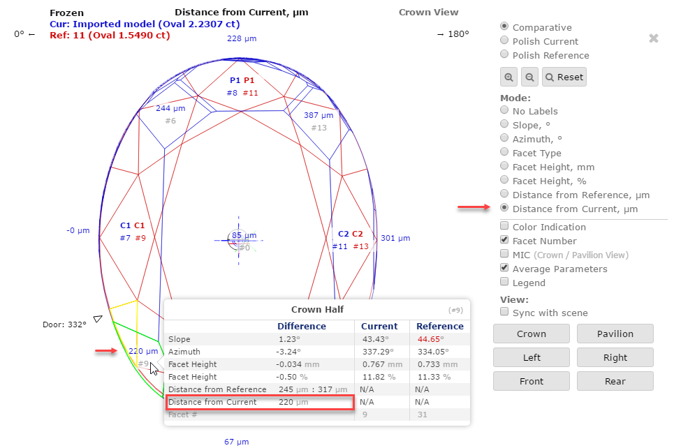
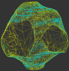
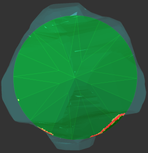
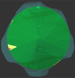
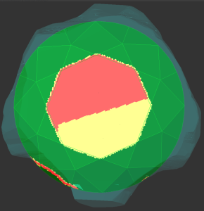
Comparative I3D Mini View - Distance from Reference/Current
For the Comparative I3D Mini View, two new modes are added:
- Distance from Reference, µm
- Distance from Current, µm
Distance from Reference, µm | Distance from Current, µm |
|---|---|
|
|
|
|
Notes on meaning: | |
|
|
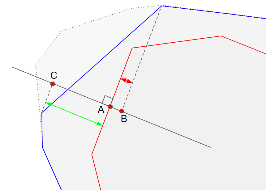
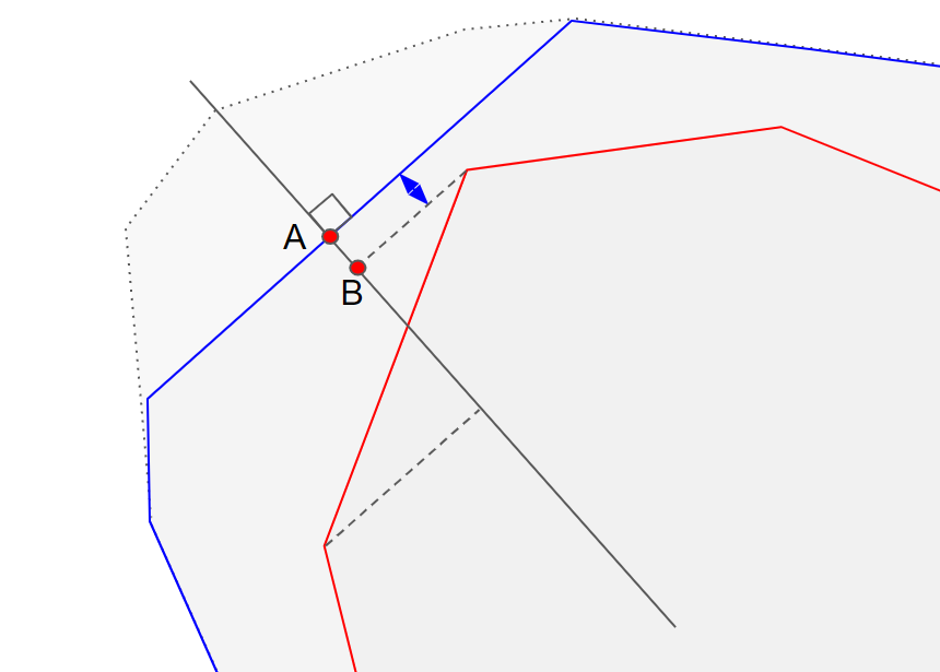
Here is an example:
New Smart Recut Parameters
The new parameter is added to the appraisers used by the Smart Recut algorithms.
SquareDeviation Tolerance
The parameter is used in the same way as the Square Deviation of the Oval cut. Unlike Square Deviation, the SquareDeviationTolerance (used by Smart Recut only) is set via presets and limits not the value of the parameter, but its deviation from the value of the starting model.
Calculation
The parameter is calculated in the same way as the Square Deviation of the Oval cut.
Usage and Examples
Here is an example of how the parameter affects a girdle shape and mass:
117_SM_10137_Square DeviationTolerance.ox2z
Reporting
| Reported in | Section | Values | Units | Bookmarks | Name in Reports |
|---|---|---|---|---|---|
None | NA | NA | NA | NA | NA |
Visualization in Appraisers
- MyAnyCutOpt | MyAnyCut
- CushionRectangular_Opt | CushionRectangular
- CushionSquare_Opt | CushionSquare
| Value | Units | Bookmark | Tab | Parameter Name | Comment |
|---|---|---|---|---|---|
| Avg (the only value) | None | NA | Cut | SquareDeviationTolerance | Visible only when presets are displayed. |
G1 Galahad
New Features
For the G1 Galahad mode, the new features were added. As this functionality is shared with the Galahad Compass product, see details in the Galahad Compass documentation:
- Release notes 2020.10.21 - Carbon Compass 1.1.13 (public)
- Release notes for the currently developed Galahad Compass release (internal)
Here is a brief overview of what is new:
- Workflow improvements
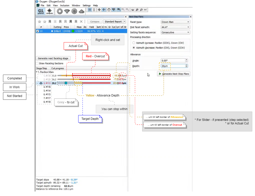
Actual Cut and 4 Colors for Steps
Order of Work - Stages and Steps
Actual Cut Model
Protection of Overcut Area ("lock" icon)
Slope Allowance Parameter
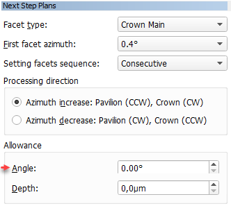
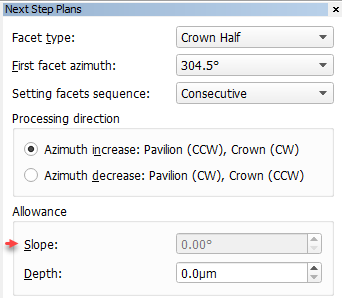
In the Next Step Plans panel, the Allowance section, the Angle parameter is renamed to Slope. The usage of the parameter is temporarily blocked (next step calculation does not consider this parameter) due to technical reasons (planned to be restored in the upcoming releases).
| Was | Now |
|---|---|
|
|
DZ Color Estimation - New Approach and Progress Bar
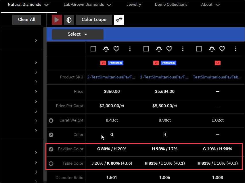
Previously for DZ Color Estimation , the calculation of Table Color was performed after the Pavilion Color for all the solutions - the process could take time but the progress was not anyhow displayed within the system. This caused the cases when the export to Cutwise could have been started before the calculation is finished thus the data uploaded to Cutwise did not contain the Table Color information. Now the Pavilion Color and Table Color are calculated together for each solution and the entire progress is indicated:
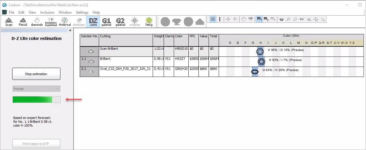
This approach guarantees that during export to Cutwise all the solutions will be exported with information about both Pavilion and Table Colors.
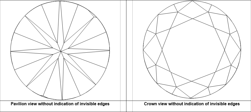
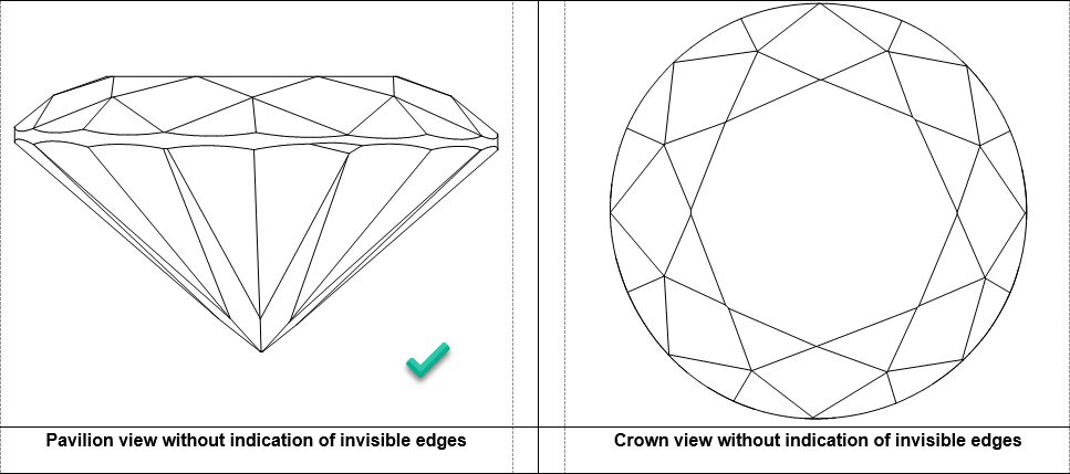
Polish RTF Reports - Views without Invisible Edges with Rotation
In the Polish RTF Full Report, there are Pavilion and Crown views without indication of invisible edges (PAVILION_VIEW and CROWN_VIEW bookmarks):
Now you can change the rotation of the model presented on these images. To do this:
- In the template, locate PAVILION_VIEW or CROWN_VIEW bookmark.
Replace bookmarked text as follows:
Was Now Comment [Width=73;Height=73;]
[Width=74;Height=74;PictureID=DRAW_DIAMOND;PavilionView=1;
Circle=0;Parameter=0;FontSize=0;X=22.5;Y=90;]X and Y with values are responsible for rotation. - Make sure, your bookmark continues to enclose the parameters, including brackets.
- Save the template.
Also, other Polish RTF reports support adding the same images with the rotation you need.
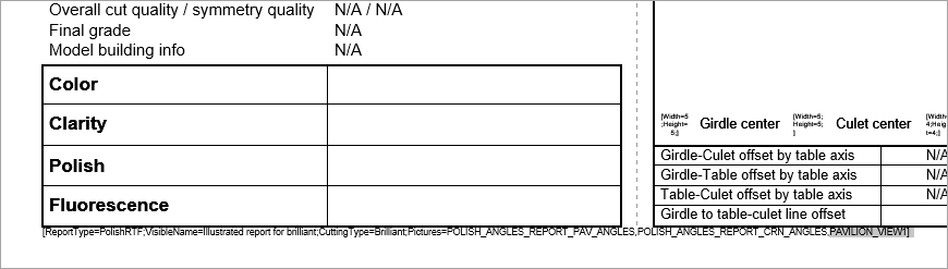
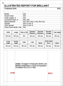
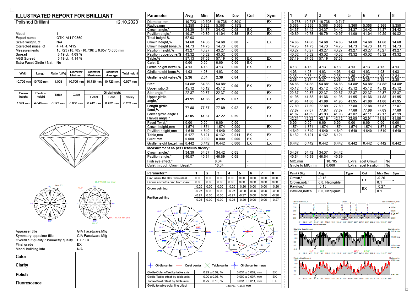
Below is the example showing how the rotated Pavilion view without invisible edges can replace the standard image in the Polish RTF Illustrated report for brilliant:
- Open the template you want to change via the right panel > Polish Report > Open Templates Folder, then opening the template file in MS Word.
- Delete the bookmark of the image we want to replace.
In this position, insert the string:
[Width=74;Height=74;PictureID=DRAW_DIAMOND;PavilionView=1;Circle=0;Parameter=0;FontSize=0;X=22.5;Y=90;]
- Highlight this string including brackets, then insert MS Word bookmark PAVILION_VIEW1.
- At the very bottom of the page, in the small font string, at the end of the string but before closing square bracket, put comma then (without space) PAVILION_VIEW1.
If necessary, to set boundaries for your image, insert columns or/and rows using the MS Word Table tool.
Save changed report template.
Note
If you want to save changes as a separate template, use Save As - before saving, in the small font string, change the VisibleName parameter.
The resulting report will look like:
Cutwise Integration - Upload to Cutwise vs Manual
When using Integration with Cutwise, you have two ways of uploading your data to Cutwise:
- Standard, automatic: via the Upload to Cutwise button in HP Carbon
- Manual: uploading models/reports directly (for example, as DMC files, including the ones obtained from the old HP Oxygen) via uploader
It is important to remember, that if you use the Upload to Cutwise function in HP Carbon, you should not use the manual approach for the same data, because after Upload to Cutwise is used if you try to manually upload the same models/reports, you will not see the new data in Cutwise - the one previously uploaded from the system with the Upload to Cutwise function will stay unchanged.
New Logo and Icons
HP Carbon now has the new logo:

And icons: 

Fixed Problems and Improvements
The following fixes for the known problems and improvements are implemented:
For Comparative I3D Mini View, synchronization with the Scene did not work in some cases - now this is fixed.
Models in Comparative Reports are aligned by the Current model now and in particular in Comparative I3D Mini View. Due to the modification of models' alignment calculation results in Comparative Reports is changed.
- Facet Marking transfer for some cuttings is improved.
- To improve Smart Recut allocation for the big (5ct+) round stones, to the "MyRound | GIA Facetware + MyRound" appraiser, the "MyRound_ H&A 5ct+" profile, the appropriate presets are added.
- Minor further improvements are made for the Smart Recut mechanism of creating girdle extra facets. Read about this mechanism improvement in the previous release on the 2020-08-11 - HP Carbon 1.0.0 page.
- For the Princess cutting, the model building is improved - the Crown is now built better.
- For the Smart Recut, when working with multi-diamond solutions from rough , described for the previous release (2020-08-11 - HP Carbon 1.0.0 page), some additional improvements are implemented:
- Facet marking is copied along with the diamonds copied during Smart Recut
- A bunch of Smart Recut attributes is copied along with the diamonds
- Cutwise integration:
- The Upload to Cutwise feature is now available on all HASP keys.
- A new basis position is supported - "Culet" (= "Heart").
- Solutions with cutting names in user locale were not uploaded to Cutwise - now this is fixed.
- The Upload to Cutwise feature is now available on all HASP keys.
- Bug with the episodic crash of the system during file opening is fixed.
Bug with the crash of the system during DZ Color calculation is fixed.
A rare bug when some system settings were reset to default values is fixed.
Autosave did not work - now this is fixed.
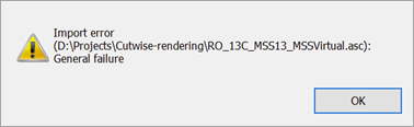
During the import of scanned ASCII, an error occurred (displayed on the picture below) caused by too strict limitations. Now limitations are eased to avoid error and allow using all scanned ASCII models.
The Rough recognition algorithm is improved.
Was Now 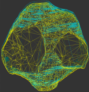
A system crash on running Smart Recut with AnyCut composite appraiser for some specific cuttings is fixed.
Fixed bug with wrong DZ Color Estimation of Main Scan if a project had several scanned or imported models. This issue was not affecting DZ estimation of solutions.
The wrong model rebuild for the Oval cutting is fixed.
In the Illustrated report for Cushion, on the image, some facet angles were not displayed - now this is fixed, all angles are presented.
Label printing is improved to work correctly with different page sizes.
The problem leading to an episodic crash of the Smart Normalize algorithm is solved.
The problem with Comparative I3D Mini View freezing in some cases is solved.
- The system rare crash during Cutwise upload is fixed.
- In the I3D Report and View, for the Sakura cutting, the Table parameters were mistakenly displayed as "0.00" while they are not calculated at all - now they are displayed as "N/A".
- Smart Recut crashed the system if Solutions Report was previously opened - now this problem is fixed.
The Facet Marking dialog:
When pointing a facet, "Tier" information was not displayed in the facet info block for "Tier 1" - now this is fixed.
For the "Cylinder" cutting, the dialog did not open (the error was displayed instead) - now this is fixed.
Add Comment